TM
MP1519 – 1X, 1.5X, 2X CHARGE PUMP 4 WHITE LED DRIVER
APPLICATION INFORMATION
Choose R1 for the desired LED current according
to the equation:
COMPONENT SELECTION
Startup
When power is applied to the BATT, driving EN
high will enable the MP1519. The MP1519 begins
by checking for open LEDs and determining the
optimum charge pump mode. The lowest charge
pump mode that allows the programmed LED
current in all LEDs is set. This will occur during
initial turn-on or during analog mode and burst
mode dimming.
31.25
R1=
ILED
Where R1 is in kΩ, and ILED is in mA. Suitable
values for R1 are greater than 1.2kꢀ.
Soft-Start
During startup and mode switching, an internal
soft-start prevents excessive input current,
preventing excessive loading of the battery or
input power source.
Shutdown
Driving EN low for more than 30µs will disable
the MP1519. For safety the MP1519 runs a
small supervisory circuit in standby to protect
the charge pump output LEDC. The circuit
shuts down when the charge pump output
returns to zero volts (this can take a few
seconds). The MP1519 is in true shutdown
mode when LEDC is zero and the 30µs time
interval has passed. The supply current should
be less than 1µA.
Burst Mode Dimming
To dim the part using burst mode, drive EN with a
PWM signal. Each time EN is driven high, the
MP1519 goes through the initial startup routine
and checks for open LEDs, and the charge pump
step-up mode is reset.
When EN goes low, the LED current immediately
goes to zero. After EN is held low for 30µs or
longer, and LEDC falls below GND, the MP1519
operating current drops below 1µA to improve
battery life. Maintain the frequency of the PWM
signal between 50Hz and 50KHz. Going above
50KHz the accuracy of the PWM signal will be
degraded due to the startup time, and below
50Hz, the LED flicker will be evident to the eye.
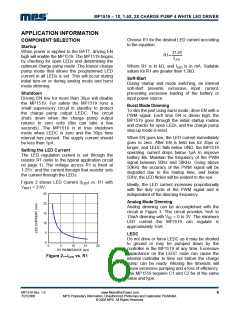
Setting the LED Current
The LED regulation current is set through the
resistor R1 (refer to the typical application circuit
on page 1). The voltage across R1 is fixed at
1.25V, and the current through that resistor sets
the current through the LEDs.
Figure 2 shows LED Current (ILED) vs. R1 with
Ideally, the LED current increases proportionally
with the duty cycle of the PWM signal and is
independent of the dimming frequency.
VBATT = 3.6V.
25
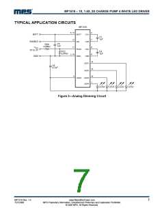
Analog Mode Dimming
20
15
10
5
Analog dimming can be accomplished with the
circuit in Figure 3. The circuit provides 1mA to
15mA dimming with VDC = 0 to 3V. The minimum
LED current the MP1519 can regulate is
approximately 1mA.
LEDC
Do not drive or force LEDC as it may be shorted
to ground or may be pumped down by the
controller in the MP1519 at any time. Excessive
capacitance on the LEDC node can cause the
internal controller to time out before the charge
pump can be ready. Missing the timeouts will
cause excessive pumping and a loss of efficiency.
The MP1519 requires C1 and C2 be of the same
value and type.
0
0
5
10
15
20
Figure 2—ILED vs. R1
MP1519 Rev. 1.9
7/27/2006
www.MonolithicPower.com
MPS Proprietary Information. Unauthorized Photocopy and Duplication Prohibited.
© 2006 MPS. All Rights Reserved.
6

 MPS [ MONOLITHIC POWER SYSTEMS ]