Model Selection Guide
Input
Output
Voltage Current
(VDC) (mA, Max) (mA, Min)
Load
Regulation
(%, Max)
15.0
9.0
Fuse Rating
Slow-Blow
(mA)
500
Model
Number
Efficiency
(%, Typ)
Voltage (VDC)
Nominal
Current (mA)
Full-Load No-Load
Current
Range
4.5 - 5.5
4.5 - 5.5
4.5 - 5.5
4.5 - 5.5
4.5 - 5.5
10.8 - 13.2
10.8 - 13.2
10.8 - 13.2
10.8 - 13.2
3.0 - 3.6
3.0 - 3.6
3.0 - 3.6
3.0 - 3.6
LF101ES
LF102ES
LF103ES
LF104ES
LF109ES
LF111ES
LF112ES
LF113ES
LF114ES
LF151ES
LF152ES
LF153ES
LF159ES
5
5
5
5
5
12
12
12
12
3.3
3.3
3.3
3.3
260
263
253
256
277
121
114
114
113
409
446
433
415
30
30
30
30
30
15
15
15
15
55
55
55
55
5.0
9.0
12.0
15.0
3.3
5.0
9.0
12.0
15.0
5.0
200.0
111.0
84.0
20.0
23.0
17.0
13.0
30.0
20.0
23.0
17.0
13.0
20.0
23.0
17.0
30.0
77
76
79
78
72
69
73
73
74
74
68
70
73
500
500
500
500
200
200
200
200
750
750
750
750
7.5
7.0
15.0
15.0
9.0
7.5
7.0
15.0
9.0
7.5
67.0
300.0
200.0
111.0
84.0
67.0
200.0
111.0
84.0
9.0
12.0
3.3
300.0
15.0
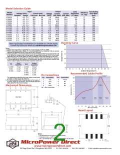
Derating Curve
Other input/output combinations are available (i.e. 24 VDC Input).
Contact the factory for details at: sales@micropowerdirect.com
Notes:
1. Output load regulation is specified for a load change of 10% to 100%.
2. When measuring output ripple, it is recommended that an external 0.33 µF ceramic
capacitor be placed from the +Vout pin to the -Vout pin.
3. During operation, care must be taken not to exceed the specified input range of the unit
or to allow the output load to drop below the specified minimum (10% of full load).
Operating the unit under either of these conditions could cause damage to the unit.
4. These converters are specified for operation without external components. However,
in some applications the addition of input/output capacitors will enhance stability and
reduce output ripple. Recommended capacitor values are:
Input
Capacitor
Output
Capacitor
Vin
Vout
3.3 VDC
5 VDC
12 VDC
4.7 µF
4.7 µF
2.2 µF
3.3 VDC
5 VDC
9 VDC
12 VDC
15 VDC
10.0 µF
10.0 µF
4.7 µF
2.2 µF
1.0 µF
Recommended Solder Profile
Pin Connections
For applications requiring very low output noise levels,
a simple LC filter should be effective.
Pin Description
Pin Description
1
2
3
4
-Vin
+Vin
NC
5
6
7
8
+Vout
NC
5. It is recommended that a fuse be used on the input of
a power supply for protection. See the Model Selection
table above for the correct rating.
NC
-Vout
NC
Mechanical Dimensions
NC = No Connection
Board Layout
Notes:
• All dimensions are typical in inches (mm)
• Tolerance x.xx = 0.01 ( 0.25)
• Pin 1 is marked by a “dot” or indentation on the unit
MicroPower Direct
•
www.micropowerdirect.com
292 Page Street Ste D Stoughton, MA 02072
•
TEL: (781) 344-8226
FAX: (781) 344-8481
•
E-Mail: sales@micropowerdirect.com

 MPD [ MICROPOWER DIRECT, LLC ]