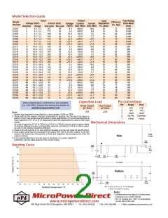
Model Selection Guide
Input
Output
Voltage Current
(VDC) (mA, Max) (mA, Min)
Load
Regulation
Fuse Rating
Slow-Blow
(mA)
1,000
1,000
1,000
1,000
1,000
1,000
1,000
500
Model
Efficiency
(%, Typ)
Voltage (VDC)
Number
Current (mA)
Full-Load No-Load
Current
(%, Max)
20
10
10
10
10
10
10
20
10
10
10
10
10
10
20
10
10
10
10
10
10
20
10
10
10
10
10
10
Nominal
5
Range
D201I
D202I
D203I
D204I
D205I
D206I
D207I
D211I
D212I
D213I
D214I
D215I
D216I
D217I
D221I
D222I
D223I
D224I
D225I
D226I
D227I
D231I
D232I
D233I
D234I
D235I
D236I
D237I
4.5 - 5.5
4.5 - 5.5
4.5 - 5.5
4.5 - 5.5
4.5 - 5.5
4.5 - 5.5
4.5 - 5.5
367
512
500
500
555
512
500
169
216
203
203
222
203
203
76
105
102
101
111
101
101
45
30
30
30
30
30
30
30
20
20
20
20
20
20
20
10
10
10
10
10
10
10
6
3.3
5.0
12.0
15.0
5.0
12.0
15.0
3.3
400.0
400.0
165.0
133.0
200.0
83.3
10.0
8.0
3.5
2.7
4.0
1.7
1.4
10.0
8.0
3.5
2.7
4.0
1.7
1.4
10.0
8.0
3.5
2.7
4.0
1.7
1.4
10.0
8.0
3.5
2.7
4.0
1.7
1.4
72
78
82
82
72
78
80
65
77
82
82
75
82
82
72
79
80
82
75
82
82
60
77
78
78
73
80
80
5
5
5
5
5
5
66.6
12
12
12
12
12
12
12
24
24
24
24
24
24
24
48
48
48
48
48
48
48
10.8 - 13.2
10.8 - 13.2
10.8 - 13.2
10.8 - 13.2
10.8 - 13.2
10.8 - 13.2
10.8 - 13.2
21.6 - 26.4
21.6 - 26.4
21.6 - 26.4
21.6 - 26.4
21.6 - 26.4
21.6 - 26.4
21.6 - 26.4
43.2 - 52.8
43.2 - 52.8
43.2 - 52.8
43.2 - 52.8
43.2 - 52.8
43.2 - 52.8
43.2 - 52.8
400.0
400.0
165.0
133.0
200.0
83.3
5.0
500
500
500
500
500
500
200
200
200
200
200
200
200
100
100
100
12.0
15.0
5.0
12.0
15.0
3.3
66.6
400.0
400.0
165.0
133.0
200.0
83.3
5.0
12.0
15.0
5.0
12.0
15.0
3.3
66.6
400.0
400.0
165.0
133.0
200.0
83.3
54
53
53
57
52
52
6
6
6
6
6
6
5.0
12.0
15.0
5.0
12.0
15.0
100
100
100
100
66.6
Pin Connections
Capacitive Load
Other input/output combinations are available
(i.e. 24.0 VDC). Contact the factory for details at:
sales@micropowerdirect.com
Pin
Single
Dual
Single Output
Dual Output
1
2
5
6
7
+Vin
-Vin
-Vout
No Pin Common
+Vout +Vout
+Vin
-Vin
-Vout
(μF Max)
(μF Max)
470
220
Notes:
1. Output load regulation is specified for a load change of 20% to 100%.
2. These units do not require external components to operate, but the use of an input ca-
pacitor (10 μF) may enhance performance in some applications. It is recommended that an
input capacitor of 4.7 uF to 47 uF (dependent upon the application) be used on 48V input
model.
An output capacitor (4.7 μF to 220 μF or 4.7 μF to 100 μF) may be used to reduce ripple.
To improve EMI performance, a simple filter network consisting of a 10 uF to 100 uF capaci-
tor and 12 uH inductor should be effective.
Mechanical Dimensions
3. These units will operate at no load without damage, but may not meet all specifications.
4. Dual output units may be connected to provide a 10V, 24V or 30 VDC output. To do this,
connect the load across the positive (+Vout) and negative (-Vout) outputs and float the
output common.
5. It is recommended that a fuse be used on the input of a power supply for
protection. See the table above for the correct rating.
Derating Curve
Notes:
•
All dimensions are typical in inches (mm) •
Tolerance x.xx = 0.01 ( 0.25) • Pin 1 is marked by a “dot” or indentation
on the side of the unit
MicroPower Direct
•
www.micropowerdirect.com
292 Page Street Ste D Stoughton, MA 02072
•
TEL: (781) 344-8226
FAX: (781) 344-8481
•
E-Mail: sales@micropowerdirect.com

 MPD [ MICROPOWER DIRECT, LLC ]