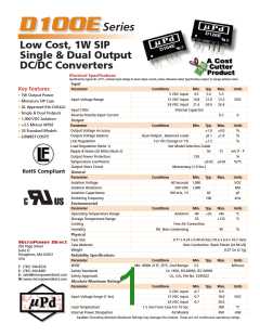
Model Selection Guide
Input
Output
Voltage Current
(VDC) (mA, Max) (mA, Min)
Load
Regulation
(%, Max)
Fuse Rating
Slow-Blow
(mA)
Model
Efficiency
(%, Typ)
Voltage (VDC)
Number
Current (mA)
Full-Load No-Load
Current
Nominal
5
Range
D101E
D102E
D103E
D104E
D105E
D106E
D107E
D108E
D111E
D112E
D113E
D114E
D115E
D116E
D117E
D118E
D121E
D122E
D123E
D124E
D125E
D126E
D127E
D128E
4.5 - 5.5
4.5 - 5.5
4.5 - 5.5
4.5 - 5.5
4.5 - 5.5
4.5 - 5.5
4.5 - 5.5
4.5 - 5.5
10.8 - 13.2
10.8 - 13.2
10.8 - 13.2
10.8 - 13.2
10.8 - 13.2
10.8 - 13.2
10.8 - 13.2
10.8 - 13.2
21.6 - 26.4
21.6 - 26.4
21.6 - 26.4
21.6 - 26.4
21.6 - 26.4
21.6 - 26.4
21.6 - 26.4
21.6 - 26.4
278
270
260
253
278
267
256
253
114
111
105
104
113
110
105
104
56
55
52
51
56
55
52
51
30
30
30
30
30
30
30
30
15
15
15
15
15
15
15
15
8
8
8
8
8
8
8
8
5.0
9.0
12.0
15.0
5.0
200.0
111.0
83.0
67.0
100.0
56.0
42.0
33.0
200.0
111.0
83.0
67.0
100.0
56.0
42.0
33.0
200.0
111.0
83.0
67.0
100.0
56.0
20.0
12.0
9.0
7.0
10.0
6.0
5.0
4.0
20.0
12.0
9.0
7.0
10.0
6.0
5.0
4.0
20.0
12.0
9.0
7.0
10.0
6.0
15
15
15
15
15
15
15
15
15
15
15
15
15
15
15
15
15
15
15
15
15
15
15
15
72
74
77
79
72
75
78
79
73
75
79
80
74
76
79
80
74
76
80
81
74
76
80
81
500
500
500
500
500
500
500
500
200
200
200
200
200
200
200
200
100
100
100
100
100
100
100
100
5
5
5
5
5
5
5
12
12
12
12
12
12
12
12
24
24
24
24
24
24
24
24
9.0
12.0
15.0
5.0
9.0
12.0
15.0
5.0
9.0
12.0
15.0
5.0
9.0
12.0
15.0
5.0
9.0
12.0
15.0
42.0
33.0
5.0
4.0
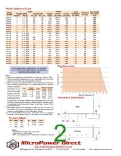
Derating Curve
Other input/output combinations are available
(i.e. 3.3 VDC). Contact the factory for details at:
sales@micropowerdirect.com
Notes:
1. Output load regulation is specified for a load change of 10% to 100%.
2. These units should not be operated with a load under 10% of full load.
Operation at no-load may cause damage to the unit.
3. These converters will operate without external components. However,
when measuring output ripple, it is recommended that an external
ceramic capacitor
Output Capacitor
Single Dual
5 VDC 10.0 μF 4.7 μF
Input
Capacitor
be placed from the
+Vout pin to the
-Vout pin for single
output units and
from each output
to common for dual
output units. An in-
Vin
Vout
5 VDC
12 VDC
24 VDC
4.7 μF
2.2 μF
1.0 μF
9 VDC
4.7 μF
2.2 μF
1.0 μF
12 VDC 2.2 μF
Mechanical Dimensions
15 VDC 1.0 μF 0.47 μF
put capacitor will enhance stability over temperature and input line
variations. Recommended capacitor values are given in the table above.
For applications requiring very low output noise levels, a simple LC filter
should be effective.
4. Dual output units may be connected to provide a 10V, 18V, 24V or 30
VDC output. To do this, connect the load across the positive (+Vout) and
negative (-Vout) outputs and float the output common
5. It is recommended that a fuse be used on the input of a power supply for
protection. See the Model Selection table above for the correct rating.
Pin Connections
Pin Single
Dual
Pin
Single
Dual
1
2
4
+Vin
-Vin
+Vin
-Vin
5
6
No Pin
+Vout
Common
+Vout
-Vout
-Vout
Notes:
• All dimensions are typical in inches (mm)
• Tolerance x.xx = 0.01 ( 0.25)
• Pin 1 is marked by a “dot” or indentation on the side of the unit
MicroPower Direct
•
www.micropowerdirect.com
292 Page Street Ste D Stoughton, MA 02072
•
TEL: (781) 344-8226
FAX: (781) 344-8481
•
E-Mail: sales@micropowerdirect.com

 MPD [ MICROPOWER DIRECT, LLC ]