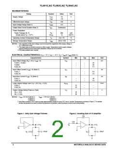
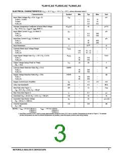
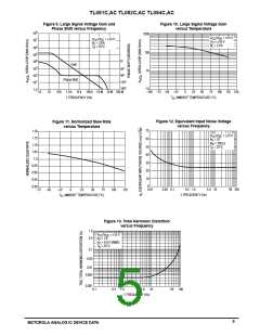
TL081C,AC TL082C,AC TL084C,AC
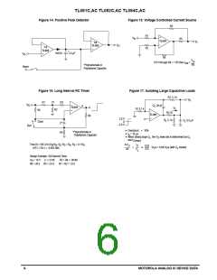
Figure 14. Positive Peak Detector
Figure 15. Voltage Controlled Current Source
R3
R1
R2
+
V
in
R5
–
TL081
I
O
1/2
–
–
V
TL082
O
1/2
+
TL082
*
1N914
1.0
µF
V
+
in
R4
V
in
R5
If R1 through R4 > > R5 then I
out
=
*Polycarbonate or
Polystyrene Capacitor
Reset
Figure 16. Long Interval RC Timer
Figure 17. Isolating Large Capacitive Loads
R2 5.1 k
V
O
R1
V1
R2
R3
V
–
R
C 20 pF
C
6
TL081
I
O
R1 5.1 k
R4
+
–
R3 10
5.1 k
TL081
R6
+
2.0 V
R
C
0.5 µF
L
L
Clear
0
C*
–2.0 V
Run
•
•
•
•
Overshoot
= 10
10%
*Polycarbonate or
Polystyrene Capacitor
R5
t
µs
s
When driving large C , the V slew rate is determined by C
L
O
L
and I
:
O(max)
Time (t) = R4 C n (V /V –V ), R = R , R = 0.1 R
6
If R1 = R2: t = 0.693 R4C
V
I
R
R
I
3
4
5
O
O
0.02
0.5
V/µ
s = 0.04 V/µs (with C shown)
L
t
C
L
Design Example: 100 Second Timer
V
= 10 V
C = l.0 mF
R5 = 2.0 k
R3 = R4 = 144 M
R1 = R2 = 1.0 k
R
R6 = 20 k
6
MOTOROLA ANALOG IC DEVICE DATA

 MOTOROLA [ MOTOROLA ]