100
50
100
T
= 150°C
J
T
= 150°C
J
100°C
50
20
10
5
100°C
25°C
2
30
20
1
0.5
25°C
0.2
0.1
10
5
0.05
0.02
0.01
0
20
40
60
80
100
120
140
160
180 200
V
, REVERSE VOLTAGE (VOLTS)
R
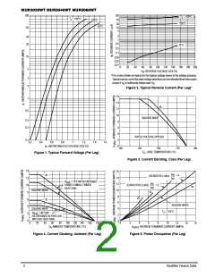
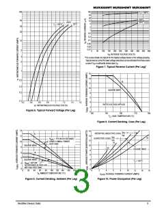
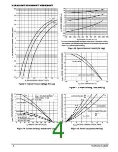
*The curves shown are typical for the highest voltage device in the voltage grouping.
Typicalreversecurrentforlowervoltageselectionscanbeestimatedfromthesesame
3
2
curves if V is sufficiently below rated V
.
R
R
Figure 2. Typical Reverse Current (Per Leg)*
16
14
12
10
8
1
dc
0.5
SQUARE WAVE
0.3
0.2
6
4
RATED VOLTAGE APPLIED
0.1
2
0.2
0.4
0.6
0.8
1
1.2
1.4
1.6
v , INSTANTANEOUS VOLTAGE (VOLTS)
0
F
140
150
160
170
C)
180
T
, CASE TEMPERATURE (°
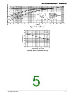
Figure 1. Typical Forward Voltage (Per Leg)
C
Figure 3. Current Derating, Case (Per Leg)
14
12
10
8
16
14
12
10
I
I
dc
PK =
AV
π
(RESISTIVE LOAD)
R
= 15°C/W AS OBTAINED
θ
JA
I
I
PK
USING A SMALL FINNED
HEAT SINK.
(CAPACITIVE LOAD)
20
= 5
dc
AV
10
SQUARE WAVE
8
6
dc
6
4
SQUARE WAVE
SQUARE WAVE
4
2
0
T
= 125
10
°C
J
R
= 40°C/W
AS OBTAINED IN FREE AIR
WITH NO HEAT SINK.
2
0
θ
JA
0
20
40
60
80
100
120 140
C)
160
180 200
0
2
4
6
8
12
14
16
T , AMBIENT TEMPERATURE (
°
I
, AVERAGE FORWARD CURRENT (AMPS)
A
F(AV)
Figure 4. Current Derating, Ambient (Per Leg)
Figure 5. Power Dissipation (Per Leg)
2
Rectifier Device Data

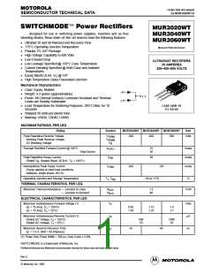
 MOTOROLA [ MOTOROLA ]