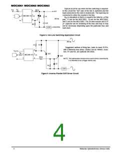
Typical circuit for use when hot line switching is required.
In this circuit the “hot” side of the line is switched and the
load connected to the cold or neutral side. The load may be
connected to either the neutral or hot line.
V
R
in
CC
360 Ω
1
6
5
HOT
2
3
MOC3061–63
39
R
is calculated so that I is equal to the rated I of the
in
F
FT
240 Vac
part, 15 mA for the MOC3061, 10 mA for the MOC3062,
and 5 mA for the MOC3063. The 39 ohm resistor and 0.01
µF capacitor are for snubbing of the triac and may or may
not be necessary depending upon the particular triac and
load used.
4
0.01
LOAD
360
NEUTRAL
Figure 8. Hot–Line Switching Application Circuit
240 Vac
D1
R1
Suggested method of firing two, back–to–back SCR’s,
with a Motorola triac driver. Diodes can be 1N4001; resis-
tors, R1 and R2, are optional 330 ohms.
1
2
6
5
V
CC
R
in
SCR
MOC3061–63
SCR
360
Ω
3
4
NOTE: This optoisolator should not be used to drive a load directly.
It is intended to be a trigger device only.
D2
R2
LOAD
Figure 9. Inverse–Parallel SCR Driver Circuit
4
Motorola Optoelectronics Device Data

 MOTOROLA [ MOTOROLA ]