Freescale Semiconductor, Inc.
systems where system integrity must be ensured over the life
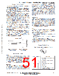
PRINCIPLE OF OPERATION
of the vehicle. A fourth “plate’’ is used in the g–cell as a self–
test plate. When the user applies a logic high input to the
self–test pin, a calibrated potential is applied across the
self–test plate and the moveable plate. The resulting elec-
The Motorola accelerometer is a surface–micromachined
integrated–circuit accelerometer.
The device consists of a surface micromachined capaci-
tive sensing cell (g–cell) and a CMOS signal conditioning
ASIC contained in a single integrated circuit package. The
sensing element is sealed hermetically at the wafer level
using a bulk micromachined “cap’’ wafer.
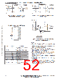
The g–cell is a mechanical structure formed from semicon-
ductor materials (polysilicon) using semiconductor pro-
cesses (masking and etching). It can be modeled as two
stationary plates with a moveable plate in–between. The
center plate can be deflected from its rest position by sub-
jecting the system to an acceleration (Figure 2).
When the center plate deflects, the distance from it to one
fixed plate will increase by the same amount that the dis-
tance to the other plate decreases. The change in distance is
a measure of acceleration.
The g–cell plates form two back–to–back capacitors
(Figure 3). As the center plate moves with acceleration, the
distance between the plates changes and each capacitor’s
value will change, (C = Aε/D). Where A is the area of the
plate, ε is the dielectric constant, and D is the distance
between the plates.
1
2 2
trostatic force (Fe = / AV /d ) causes the center plate to
2
deflect. The resultant deflection is measured by the accel-
erometer’s control ASIC and a proportional output voltage
results. This procedure assures that both the mechanical
(g–cell) and electronic sections of the accelerometer are
functioning.
Ratiometricity
Ratiometricity simply means that the output offset voltage
and sensitivity will scale linearly with applied supply voltage.
That is, as you increase supply voltage the sensitivity and
offset increase linearly; as supply voltage decreases, offset
and sensitivity decrease linearly. This is a key feature when
interfacing to a microcontroller or an A/D converter because
it provides system level cancellation of supply induced errors
in the analog to digital conversion process.
Status
Motorola accelerometers include fault detection circuitry
and a fault latch. The Status pin is an output from the fault
latch, OR’d with self–test, and is set high whenever one (or
more) of the following events occur:
The CMOS ASIC uses switched capacitor techniques to
measure the g–cell capacitors and extract the acceleration
data from the difference between the two capacitors. The
ASIC also signal conditions and filters (switched capacitor)
the signal, providing a high level output voltage that is ratio-
metric and proportional to acceleration.
•
•
•
Supply voltage falls below the Low Voltage Detect (LVD)
voltage threshold
Clock oscillator falls below the clock monitor minimum
frequency
Acceleration
Parity of the EPROM bits becomes odd in number.
The fault latch can be reset by a rising edge on the self–
test input pin, unless one (or more) of the fault conditions
continues to exist.
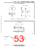
BASIC CONNECTIONS
Pinout Description for the Wingback Package
Figure 2. Transducer
Physical Model
Figure 3. Equivalent
Circuit Model
1
2
3
4
5
6
SPECIAL FEATURES
Filtering
The Motorola accelerometers contain an onboard 4–pole
switched capacitor filter. A Bessel implementation is used
because it provides a maximally flat delay response (linear
phase) thus preserving pulse shape integrity. Because the fil-
ter is realized using switched capacitor techniques, there is
no requirement for external passive components (resistors
and capacitors) to set the cut–off frequency.
Pin No.
Pin Name
Description
1
—
Leave unconnected or connect to sig-
nal ground
2
3
ST
Logic input pin to initiate self test
Output voltage
V
OUT
4
Status
Logic output pin to indicate fault
Signal ground
Self–Test
5
V
SS
The sensor provides a self–test feature that allows the
verification of the mechanical and electrical integrity of the
accelerometer at any time before or after installation. This
feature is critical in applications such as automotive airbag
6
V
Supply voltage (5 V)
DD
—
Wings
Support pins, internally connected to
lead frame. Tie to V
.
SS
Motorola Sensor Device Data
www.motorola.com/semiconductors
Go to: www.freescale.com
2–15
For More Information On This Product,

 MOTOROLA [ MOTOROLA ]