MC54/74HC4051 MC74HC4052 MC54/74HC4053
V
CC
V
IS
A
V
CC
16
16
R
V
L
OS
ON/OFF
OFF/ON
COMMON O/I
f
ON
in
NC
ANALOG I/O
0.1µF
OFF
V
R
L
R
EE
C *
L
C *
V
L
L
CC
R
6
7
8
L
6
7
8
11
V
EE
CHANNEL SELECT
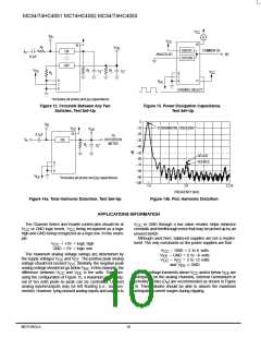
*Includes all probe and jig capacitance
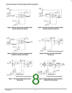
Figure 12. Crosstalk Between Any Two
Switches, Test Set–Up
Figure 13. Power Dissipation Capacitance,
Test Set–Up
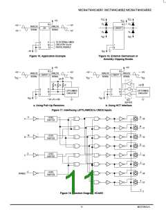
0
–10
–20
–30
–40
V
IS
FUNDAMENTAL FREQUENCY
V
CC
16
V
OS
0.1µF
TO
f
in
DISTORTION
METER
ON
R
L
C *
L
–50
–60
–70
DEVICE
SOURCE
6
7
8
–80
–90
V
EE
*Includes all probe and jig capacitance
–100
1.0
2.0
3.125
FREQUENCY (kHz)
Figure 14a. Total Harmonic Distortion, Test Set–Up
Figure 14b. Plot, Harmonic Distortion
APPLICATIONS INFORMATION
The Channel Select and Enable control pins should be at
or GND logic levels. V being recognized as a logic
high and GND being recognized as a logic low. In this exam-
ple:
V
or GND through a low value resistor helps minimize
CC
V
crosstalk and feedthrough noise that may be picked up by an
unused switch.
Although used here, balanced supplies are not a require-
ment. The only constraints on the power supplies are that:
CC
CC
V
= +5V = logic high
CC
GND = 0V = logic low
V
– GND = 2 to 6 volts
– GND = 0 to –6 volts
CC
The maximum analog voltage swings are determined by
V
V
EE
the supply voltages V
voltage should not exceed V . Similarly, the negative peak
analog voltage should not go below V . In this example, the
difference between V
and V . The positive peak analog
CC
EE
– V
= 2 to 12 volts
≤ GND
CC
EE
CC
and V
EE
EE
When voltage transients above V
and/or below V
are
EE
and V
is ten volts. Therefore,
EE
CC
CC
anticipated on the analog channels, external Germanium or
Schottky diodes (D ) are recommended as shown in Figure
16. These diodes should be able to absorb the maximum
anticipated current surges during clipping.
using the configuration of Figure 15, a maximum analog sig-
nal of ten volts peak–to–peak can be controlled. Unused
analog inputs/outputs may be left floating (i.e., not con-
nected). However, tying unused analog inputs and outputs to
x
MOTOROLA
10
High–Speed CMOS Logic Data
DL129 — Rev 6

 MOTOROLA [ MOTOROLA ]