MAXIMUM RATINGS — continued
Rating
Symbol
Value
Unit
Volts
°C
Peak Reverse Gate Voltage
V
GRM
6
Operating Junction Temperature Range
Storage Temperature Range
T
J
–40 to +110
–40 to +150
6
T
stg
°C
(1)
Mounting Torque
—
in. lb.
1. Torque rating applies with use of compression washer (B52200F006). Mounting torque in excess of 6 in. lb. does not appreciably lower
case-to-sink thermal resistance. Anode lead and heatsink contact pad are common.
For soldering purposes (either terminal connection or device mounting), soldering temperatures shall not exceed +200°C. For optimum
results, an activated flux (oxide removing) is recommended.
THERMAL CHARACTERISTICS (T = 25°C, R
= 1 kΩ unless otherwise noted.)
C
GK
Characteristic
Thermal Resistance, Junction to Case
Symbol
Max
3
Unit
°C/W
°C/W
R
R
θJC
Thermal Resistance, Junction to Ambient
75
θJA
ELECTRICAL CHARACTERISTICS (T = 25°C unless otherwise noted.)
C
Characteristic
Symbol
I , I
DRM RRM
Min
Typ
Max
Unit
Peak Forward or Reverse Blocking Current
(V
AK
= Rated V
or V
, R
RRM GK
= 1000 Ohms)
T
J
T
J
= 25°C
= 110°C
—
—
—
—
10
100
µA
µA
DRM
Forward “On” Voltage
(I = 1 A Peak)
V
—
—
2.2
Volts
TM
FM
Gate Trigger Current (Continuous dc)
(V = 6 Vdc, R = 100 Ohms)
I
µA
GT
—
—
30
75
200
500
AK
(V
L
= 6 Vdc, R = 100 Ohms, T = –40°C)
AK
Gate Trigger Voltage (Continuous dc)
(V = 6 Vdc, R = 100 Ohms, R
L
C
V
Volts
GT
= 1000 Ohms)
T
T
= 25°C
0.4
0.5
0.2
—
—
—
0.8
1
—
AK GK
L
J
(V
R
= Rated V
, R = 3000 Ohms,
AK DRM L
= 1000 Ohms, T = 110°C)
= –40°C
GK
Holding Current
(V = 12 Vdc, R
J
J
T
J
T
J
T
J
= 25°C
= –40°C
= +110°C
I
0.3
0.4
0.14
—
—
—
3
6
2
mA
HX
= 1000 Ohms)
GK
D
Forward Voltage Application Rate
dv/dt
—
8
—
V/µs
(T = 110°C, R
= 1000 Ohms, V = Rated V )
J
GK
D
DRM
Turn-On Time
Turn-Off Time
t
—
—
1.2
40
—
—
µs
µs
gt
t
q
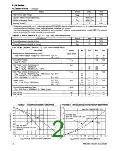
FIGURE 1 – AVERAGE CURRENT DERATING
FIGURE 2 – MAXIMUM ON-STATE POWER DISSIPATION
110
100
10
JUNCTION TEMPERATURE
≈
110°C
90
80
70
8
6
4
DC
HALF SINE WAVE
RESISTIVE OR INDUCTIVE LOAD
50 TO 400Hz.
60
50
DC
HALF SINE WAVE
RESISTIVE OR INDUCTIVE LOAD.
50 to 400 Hz
40
30
2
0
20
10
0
.4
.8
1.2
1.6
2.0
2.4
2.6
3.2
3.6
4.0
0
.4
.8
1.2
1.6
2.0
2.4
2.8
3.2
3.6
4.0
I
AVERAGE ON-STATE CURRENT (AMPERES)
I
AVERAGE ON-STATE CURRENT (AMPERES)
T(AV)
T(AV)
2
Motorola Thyristor Device Data

 MOTOROLA [ MOTOROLA ]