25
20
15
1.0
V
@ I /I = 10
C B
0.8
0.6
0.4
BE
V
@ V = 10 V
CE
BE
V
@ I /I = 10
C B
CE(sat)
10
0.2
0
T = +25°C
J
I
/I = 5.0
C B
5.0
0
20
40
60
80
100
120
C)
140
160
10
20
30
I , COLLECTOR CURRENT (mA)
C
50
100
200 300
500
T
, CASE TEMPERATURE (
°
C
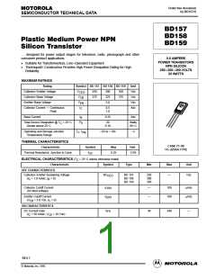
Figure 1. Power–Temperature Derating Curve
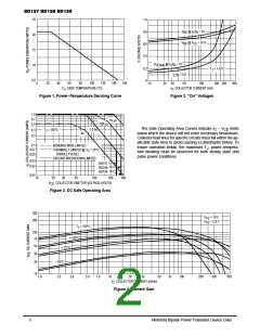
Figure 2. “On” Voltages
1.0
0.7
0.5
10
µs
500 µs
The Safe Operating Area Curves indicate I – V limits
CE
1.0 ms
C
T
= 150°C
0.3
0.2
J
dc
below which the device will not enter secondary breakdown.
Collector load lines for specific circuits must fall within the ap-
plicable Safe Area to avoid causing a catastrophic failure. To
0.1
0.07
0.05
BONDING WIRE LIMITED
THERMALLY LIMITED @ T = 25
(SINGLE PULSE)
SECOND BREAKDOWN LIMITED
insure operation below, the maximum T , power–tempera-
J
°C
C
ture derating must be observed for both steady state and
pulse power conditions.
0.03
0.02
BD157
BD158
BD159
0.01
10
20
30
50
100
200
300
V
, COLLECTOR–EMITTER VOLTAGE (VOLTS)
CE
Figure 3. DC Safe Operating Area
300
V
V
= 10 V
= 2.0 V
CE
CE
200
T
= 150°C
J
100
70
+ 100°C
50
+ 25°C
30
20
– 55°C
10
1.0
2.0
3.0
5.0
7.0
10
20
30
50
70
100
200
300
500
I
, COLLECTOR CURRENT (mAdc)
C
Figure 4. Current Gain
2
Motorola Bipolar Power Transistor Device Data

 MOTOROLA [ MOTOROLA ]