AM26LS31
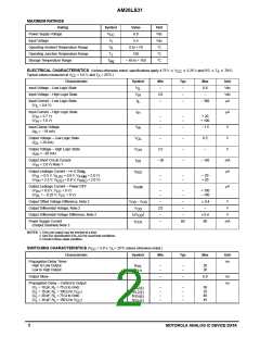
Figure 1. Three–State Enable Test Circuit and Waveforms
3.0 V or Gnd
Input
To Scope
Output
To Scope (Input)
Inv
Output
Pulse generator characteristics
= 50 Ω
Open for t
PZH(E)
Test Only
Z
o
PRR
50% Duty Cycle
, t 6 ns
1.0 MHz
+ 5 V
180
75
Non–Inv
Output
Enable
t
TLH THL
C
L
Pulse
Generator
50
3.0 V
R
– See Test Table
L
C
Includes Probe and Jig Capacitance. See Test Table.
L
3.0 V
0
3.0 V
Control
Input
1.3 V
1.3 V
Control
Input
(Enable)
(Enable)
0
t
PZL(E)
t
PHZ(E)
Output
Output
1.3 V
1.3 V
V
OH
V
0.5 V
OL
Output
Output
0 V
t
≈
≈
1.5 V
1.5 V
PZH(E)
V
OH
t
PLZ(E)
0.5 V
0 V
V
OL
0 V
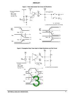
Figure 2. Propagation Delay Times Input to Output Waveforms and Test Circuit
Scope
(Output)
5.0 V
Scope
(Input)
Inv
Output
200
75
Pulse
Generator
50
Non–Inv
Output
C
= 30 pF
L
3.0 V
Enable
Pulse generator characteristics
= 50 Ω
Z
o
PRR
50% Duty Cycle
, t 6 ns
1.0 MHz
C
Includes Probe and Jig Capacitance
L
t
TLH THL
3.0 V
Input
1.3 V
1.3 V
0 V
V
t
t
t
PHL
PLH
OH
Output
1.3 V
1.3 V
V
OL
0 V
t
PLH
PHL
V
OH
Output
1.3 V
1.3 V
V
OL
0 V
3
MOTOROLA ANALOG IC DEVICE DATA

 MOTOROLA [ MOTOROLA ]