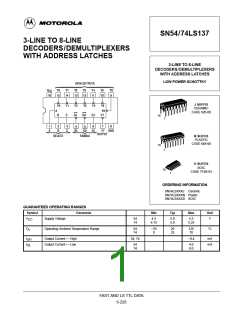
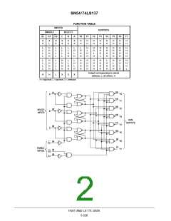
SN54/74LS137
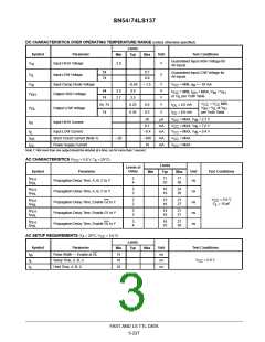
DC CHARACTERISTICS OVER OPERATING TEMPERATURE RANGE (unless otherwise specified)
Limits
Symbol
Parameter
Input HIGH Voltage
Unit
Test Conditions
Min
Typ
Max
Guaranteed Input HIGH Voltage for
All Inputs
V
2.0
V
IH
54
74
0.7
0.8
Guaranteed Input LOW Voltage for
All Inputs
V
V
V
Input LOW Voltage
V
IL
Input Clamp Diode Voltage
Output HIGH Voltage
–0.65
3.5
–1.5
V
V
V
V
V
V
= MIN, I = –18 mA
IN
IK
CC
54
74
2.5
2.7
= MIN, I
OH
= MAX, V = V
IN
CC
IH
OH
or V per Truth Table
IL
3.5
V
V
= V
CC
MIN,
= V or V
IL IH
54, 74
0.25
0.4
0.5
I
I
= 4.0 mA
= 8.0 mA
CC
IN
OL
V
OL
Output LOW Voltage
Input HIGH Current
74
0.35
V
per Truth Table
OL
20
0.1
µA
mA
mA
mA
mA
V
CC
V
CC
V
CC
V
CC
V
CC
= MAX, V = 2.7 V
IN
I
IH
= MAX, V = 7.0 V
IN
I
I
I
Input LOW Current
–0.4
–100
18
= MAX, V = 0.4 V
IN
IL
Short Circuit Current (Note 1)
Power Supply Current
–20
= MAX
= MAX
OS
CC
Note 1: Not more than one output should be shorted at a time, nor for more than 1 second.
AC CHARACTERISTICS (V
= 5.0 V, T = 25°C)
A
CC
Limits
Levels of
Delay
Symbol
Parameter
Unit
Test Conditions
Min
Typ
Max
t
t
2
4
11
25
17
38
PLH
PHL
Propagation Delay Time, A, B, C to Y
ns
t
t
3
3
16
19
24
29
PLH
PHL
Propagation Delay Time, A, B, C to Y
Propagation Delay Time, Enable G2 to Y
Propagation Delay Time, Enable G1 to Y
Propagation Delay Time, Enable GL to Y
ns
ns
ns
ns
V
C
= 5.0 V
t
t
2
2
13
16
21
27
CC
= 15 pF
PLH
PHL
L
t
t
3
3
14
18
21
27
PLH
PHL
t
t
3
4
18
25
27
38
PLH
PHL
AC SETUP REQUIREMENTS (T = 25°C, V
CC
= 5.0 V)
A
Limits
Typ
Symbol
Parameter
Pulse Width — Enable at GL
Setup Time, A, B, C
Unit
Test Conditions
Min
Max
t
t
t
15
10
10
ns
ns
ns
W
V
CC
= 5.0 V
s
Hold Time, A, B, C
h
FAST AND LS TTL DATA
5-227

 MOTOROLA [ MOTOROLA ]