MITSUBISHI SEMICONDUCTOR <TRANSISTOR ARRAY>
M54523P/FP
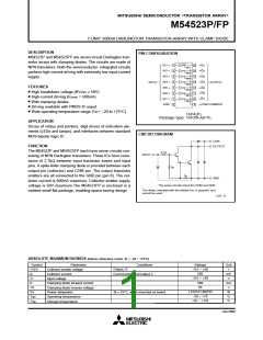
7-UNIT 500mA DARLINGTON TRANSISTOR-ARRAY WITH CLAMP DIODE
RECOMMENDED OPERATING CONDITIONS (Unless otherwise noted, Ta = –20 ~ +75°C)
Limits
typ
Symbol
VO
Parameter
Unit
V
min
0
max
50
Output voltage
—
Duty Cycle
Collector current
(Current per 1 cir-
cuit when 7 circuits
are coming on si-
multaneously)
P : no more than 8%
FP : no more than 8%
0
0
—
—
400
200
mA
IC
Duty Cycle
P : no more than 30%
FP : no more than 25%
—
—
—
25
25
IC ≤ 400mA
IC ≤ 200mA
3.85
3.4
0
“H” input voltage
“L” input voltage
VIH
VIL
V
V
0.6
ELECTRICAL CHARACTERISTICS (Unless otherwise noted, Ta = –20 ~ +75°C)
Symbol Parameter Test conditions
Limits
typ*
—
Unit
V
min
50
max
—
V
(BR) CEO Collector-emitter breakdown voltage ICEO = 100µA
—
1.2
2.4
1.6
1.8
18
VI = 3.85V, IC = 400mA
VCE(sat)
II
Collector-emitter saturation voltage
Input current
V
—
1.0
VI = 3.4V, IC = 200mA
VI = 3.85V
—
1.2
mA
VI = 25V
—
9.5
VF
IR
Clamping diode forward volltage
Clamping diode reverse current
DC amplification factor
IF = 400mA
—
1.4
2.4
100
—
V
VR = 50V
—
—
µA
—
hFE
1000
2500
VCE = 4V, IC = 350mA, Ta = 25°C
* : The typical values are those measured under ambient temperature (Ta) of 25°C. There is no guarantee that these values are obtained un-
der any conditions.
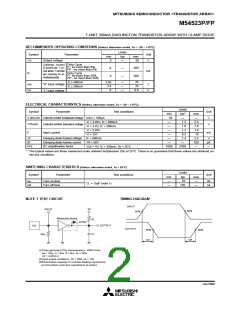
SWITCHING CHARACTERISTICS (Unless otherwise noted, Ta = 25°C)
Limits
Symbol
Parameter
Test conditions
Unit
min
—
typ
10
max
—
ns
ns
ton
toff
Turn-on time
Turn-off time
CL = 15pF (note 1)
—
120
—
TIMING DIAGRAM
NOTE 1 TEST CIRCUIT
INPUT
Vo
INPUT
50%
50%
Measured device
RL
OPEN
OUTPUT
PG
OUTPUT
50%
ton
50%
CL
50Ω
toff
(1)Pulse generator (PG) characteristics : PRR=1kHz,
tw = 10µs, tr = 6ns, tf = 6ns, Zo = 50Ω
VP
= 3.85VP-P
(2)Input-output conditions : R
(3)Electrostatic capacity C includes floating capacitance
at connections and input capacitance at probes
L
= 25Ω, Vo = 10V
L
Jan.2000

 MITSUBISHI [ Mitsubishi Group ]