BEFORE USING THIS USER’S MANUAL
This user’s manual consists of the following three chapters. Refer to the chapter appropriate to your conditions, such
as hardware design or software development. Chapter 3 also includes necessary information for systems development.
Be sure to refer to this chapter.
1. Organization
● CHAPTER 1 HARDWARE
This chapter describes features of the microcomputer and operation of each peripheral function.
● CHAPTER 2 APPLICATION
This chapter describes usage and application examples of peripheral functions, based mainly on setting examples
of related registers.
● CHAPTER 3 APPENDIX
This chapter includes necessary information for systems development using the microcomputer, electric
characteristics, a list of registers, the masking confirmation (mask ROM version), and mark specifications which
are to be submitted when ordering.
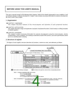
2. Structure of register
The figure of each register structure describes its functions, contents at reset, and attributes as follows :
(Note 2)
Bit attributes
Bits
(Note 1)
Contents immediately after reset release
b7 b6 b5 b4 b3 b2 b1 b0
0
CPU mode register (CPUM) [Address : 3B16
]
At reset
B
0
1
2
Name
Function
R W
b1 b0
0 0 : Single-chip mode
0
0
0
Processor mode bits
0 1 :
1 0 : Not available
1 1 :
0 : 0 page
Stack page selection bit
1 : 1 page
✕
✕
3
4
5
6
7
0
0
1
✻
Nothing arranged for these bits. These are write disabled
bits. When these bits are read out, the contents are “0.”
Fix this bit to “0.”
0 : Operating
Main clock (XIN-XOUT) stop bit
1 : Stopped
0 : X -XOUT selected
1 : XICNIN-XCOUT selected
✻
Internal system clock selection bit
: Bit in which nothing is arranged
: Bit that is not used for control of the corresponding function
Note 1. Contents immediately after reset release
0••••••“0” at reset release
1••••••“1” at reset release
Undefined••••••Undefined or reset release
••••••Contents determined by option at reset release
✻
Note 2. Bit attributes••••••The attributes of control register bits are classified into 3 bytes : read-only, write-only
and read and write. In the figure, these attributes are represented as follows :
R••••••Read
••••••Read enabled
✕••••••Read disabled
W••••••Write
••••••Write enabled
✕ ••••••Write disabled

 MITSUBISHI [ Mitsubishi Group ]