Mitsubishi microcomputers
M16C / 61 Group
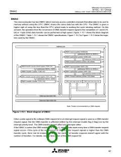
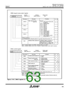
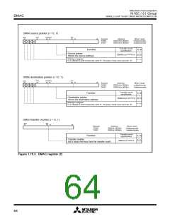
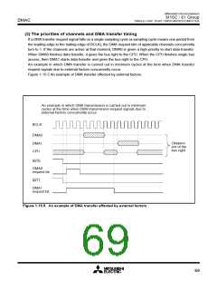
DMAC
SINGLE-CHIP 16-BIT CMOS MICROCOMPUTER
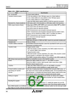
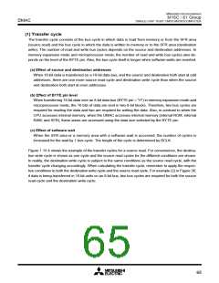
(1) Transfer cycle
The transfer cycle consists of the bus cycle in which data is read from memory or from the SFR area
(source read) and the bus cycle in which the data is written to memory or to the SFR area (destination
write). The number of read and write bus cycles depends on the source and destination addresses. In
memory expansion mode and microprocessor mode, the number of read and write bus cycles also de-
pends on the level of the BYTE pin. Also, the bus cycle itself is longer when software waits are inserted.
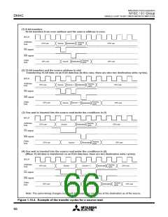
(a) Effect of source and destination addresses
When 16-bit data is transferred on a 16-bit data bus, and the source and destination both start at odd
addresses, there are one more source read cycle and destination write cycle than when the source
and destination both start at even addresses.
(b) Effect of BYTE pin level
When transferring 16-bit data over an 8-bit data bus (BYTE pin = “H”) in memory expansion mode and
microprocessor mode, the 16 bits of data are sent in two 8-bit blocks. Therefore, two bus cycles are
required for reading the data and two are required for writing the data. Also, in contrast to when the
CPU accesses internal memory, when the DMAC accesses internal memory (internal ROM, internal
RAM, and SFR), these areas are accessed using the data size selected by the BYTE pin.
(c) Effect of software wait
When the SFR area or a memory area with a software wait is accessed, the number of cycles is
increased for the wait by 1 bus cycle. The length of the cycle is determined by BCLK.
Figure 1.15.4 shows the example of the transfer cycles for a source read. For convenience, the destina-
tion write cycle is shown as one cycle and the source read cycles for the different conditions are shown.
In reality, the destination write cycle is subject to the same conditions as the source read cycle, with the
transfer cycle changing accordingly. When calculating the transfer cycle, remember to apply the respec-
tive conditions to both the destination write cycle and the source read cycle. For example (2) in Figure 36,
if data is being transferred in 16-bit units on an 8-bit bus, two bus cycles are required for both the source
read cycle and the destination write cycle.
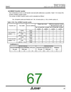
65

 MITSUBISHI [ Mitsubishi Group ]