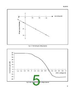
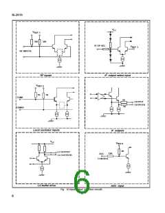
SL2015
Links and Switches
SL2015 Evaluation Board
The board is provided with the following:
AGC SELECT switch
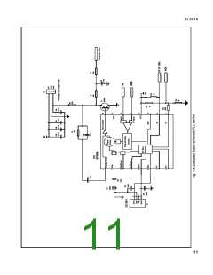
This board has been created to show the operation of the
SL2015 mixer/oscillator together with the SP5659 low phase
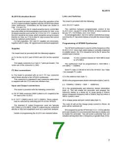
noise synthesiser. Schematics for the board are shown in
Figs. 11a and 11b.
This switches between programmable control of the
SL2015 AGC, via port P1 of the SP5659, or direct control via
the pin TP1, EXTERNAL AGC VOLTAGE.
Innormalapplication, theAGCwillbecontrolledviaaloop,
such that the IF chip which follows is fed with the desired input
level.
In a real system, the IF output would be fed to a SAW filter
thenontoeitheranFMdemodulatorsuchastheSL1466,oran
IQ downconverter such as the SL1710 or SL1711. Control of
the AGC would be via a loop, which should be set up to ensure
that the SL1466, SL1710 or other IF chip receives the correct
level for optimum performance.
For full evaluation, 30V and 5V supplies are necessary,
together with I2C data, RF signal sources and test equipment.
Programming of SP5659 Synthesiser
The SP5659 synthesiser is used to set the frequency of the
SL2015 VCO. Since high sided mixing is normally employed
in satellite tuners, the VCO should be set to the IF above the
wanted input channel.
Supplies
The board must be provided with the following supplies:
a) 5V for the SL2015 and SP5659 and 30V for the varactor
line.
Example:
To mix a wanted channel at 1020.5MHz down
to 479.5MHz.
The supply connector is a 3 pin 0.1" pitch pin header. The
centre pin of the connector is GND.
The synthesiser must be programmed to 1020.5MHz +
479.5MHz = 1500MHz.
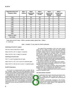
Send I2C data C2 0B B8 93 40 to the SP5659. See Table
1 for example I2C codes.
I2C Bus connections
b) The board is provided with an RJ11 I2C bus connector
which feeds directly to the SP5659 synthesiser.
C2 is the address byte (byte 1).
This connects to a standard 6-way connector cable which
0BB8istheprogrammabledividerinformation(bytes2and3).
(i.e. 1500MHz / 500kHz = 3000 = 0BB8Hex)
is supplied with the I2C/3-wire bus interface box.
Input and Output connections
93 is the programmable and reference divider information
(byte 4). This will enable the prescaler and program the
reference divider to a divide by 16 mode giving a 250kHz
phase comparator frequency with a 500kHz step size when a
4MHz crystal is used.
The board is provided with the following connectors:
a) RF I/P SMA connector (SMA1) which is AC coupled to the
RF input of the SL2015.
b) IF OUT 1 (SMA2) and IF OUT 2 (SMA5). These outputs
may be selected by switching port P0 on the SP5659.
40 is charge pump and port control data (byte 5).
The code 40 will set the charge pump current to 260uA. All
ports will be switched off.
The standard IF output frequencies used are typically
402.75MHz or 479.5MHz. Either IF output may be connected
directly to 50Ω test equipment such as a spectrum analyser.
IfitisrequiredtousetheSP5659(forVCO<2GHz)withthe
prescaler disabled it is recommended that data is initially sent
to enable the prescaler. This will avoid a potential 'lock out'
situation arising when the LO frequency is greater than 2GHz.
Details of programming the SL2015 are included below.
7

 MITEL [ MITEL NETWORKS CORPORATION ]