PDSP16510A MA
input. When DEN and DOS are both active an internal read
operation occurs, and an address generator is incremented.
DAV goes in-active in response to the DOS edge needed to
readthelastoutput, unlessBit15intheControlRegisterisset.
In this case DAV goes in-active when the next INEN edge is
received for reasons given later.
used to drive the INEN input. This then initializes a new load
operation only when the previous dump has been completed.
In such a system the INEN edge will be asynchronous to the
DIS strobe, and the set up time given in Table 1 may not be
obeyed. This will simply cause an extra input sample to be
possibly ignored, but will not cause data corruption.
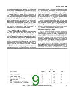
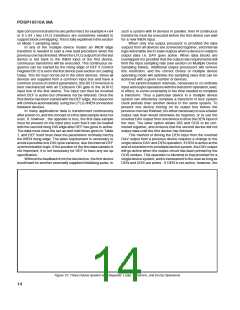
Results are transferred from the device with the rising
edge of the DOSstrobe whenDEN isactive. Thisis consistent
with using the device in a data flow architecture, as is com-
monly employed in data processing systems. In a typical
microprocessor based system, however, data is normally
expected to become valid before the end of the data strobe
produced by the processor. It is thus necessary for the user
to provide a ‘dummy’ data strobe in order to transfer data to
the outputs which can then be read by the host during the next
data strobe. In addition a further three ' dummy ' strobes are
neededeachtimeDAVgoesactiveinordertoprimetheoutput
circuitry. The actual output sequence is given in Table 3, and
illustrates that four DEN enabled DOS strobes are needed
before the first frequency bin appears on the output pins. This
is then read by the host with the fifth DOS strobe. DAV does
not go inactive until the DOS edge after the last bin appeared
on the output pins.
In host controlled systems the time to dump data could be
longer than the transform time. The dump time in such a
system will dictate the maximum sampling rate that can be
used without the loss of incoming data. In the 1024 point
mode, whenthelossofdataisnotimportant, thePDSP16510
is designed to not accept new data until the previous results
havebeendumped. Suchasystemneedsnoinputbuffer, and
INEN can be permanently tied low if the edge activated mode
is not in use. If the loss of data is to be avoided an input buffer
is needed and the host must have received all the results
before a new block of data has been loaded into the buffer.
For 256 point transforms, with host controlled dumping,
it is still possible to overlap load and dump operations. The
maximum dump times , however, must be less than the load
times to avoid data corruption. Previously converted outputs
will be actually corrupted , rather than inputs simply not being
used.
If the loss of incoming data is not important, the device
can be forced to do separate load, transform, and then dump
operations. The corruption of results will then never occur, no
matter what dump time is taken. This can be achieved by
ensuring that INEN is not active between loading a block of
data and completing the dump of the results from that data.
The same ends can be achieved if the INEN edge activated
mode ( Bit 12 reset ) is used, and the inverted DAV edge is
In addition to the above requirements it is necessary to
provide at least four DOS strobes after DEF has gone in-
active, but before DAV goes active. These initialize the
internal address counters and do not rely on DEN also being
active. They are needed every time DEF has been used to
change the operating mode.
16510A
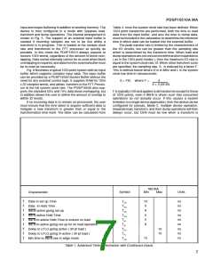
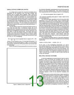
Symbol
Charactreristic
Min
Max
Units
DEN Set Up Time
†
†
†
†
†
†
†
†
†
TPS
TPW
TPH
TVI
10
10
5
ns
ns
ns
ns
ns
ns
ns
ns
ns
Host Strobe Width
DEN Hold Time
DAV in-active going Delay ( 30 pf load )
Output Enable Time ( see Fig 13 )
Output Data Delay Time ( 30 pf load )
Output Disable Time ( see Fig 13 )
Read Cycle Times
10
10
15
10
TLZ
TDD
THZ
TRC
TOH
25
2
Old Data Hold Time
Table 3. Host Controlled Output Timing. ( Advanced Data )
10

 MITEL [ MITEL NETWORKS CORPORATION ]