PDSP16116
NORMAL MODE OPERATION
of CLK. The X and Y port registers are individually enabled by
CEX CEY
quired to be permanently enabled, then these signals may be
tied to ground.
When the MBFP mode select input is held low the ‘Normal’
mode of operation is selected. This mode supports all complex
multiply operations that do not require block floating point
arithmetic.
the
and
signals respectively. If the registers are re-
Complex two’s complement fractional data is loaded into the
X and Y input registers via the X and Y Ports on the rising edge
The Real and Imaginary components of the fractional data
are each assumed to have the following format:
Bit Number
Weighting
15 14 13 12 11 10
9
8
7
6
5
4
3
2
1
0
1
2
3
4
5
6
7
8
9
15
S
2– 2– 2– 2– 2– 2– 2– 2– 2– 2–10 2–11 2–12 2–13 2–14 2–
Where S = sign bit, which has an effective weighting of 220
The value of the 16-bit two’s complement word is (213S)1(bit143221)1(bit133222)1(bit123223) …
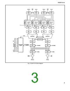
Multiplier Stage
Oneachclockcyclethecontentsoftheinputregistersarepassed
to the four multipliers to start a new complex multiply operation.
Each complex multiply operation requires four partial products
(XR3YR), (XR3YI), (XI3YR), (XI3YI), all of which are calculated
in parallel by the four 16316 multipliers. Only one clock cycle is
required to complete the multiply stage before the multiplier results
are loaded into the multiplier output registers for passing on to the
adder/ subtractors in the next cycle. Each multiplier produces a 31-
bit result with the duplicate sign bit eliminated. The format of the
output data from the multipliers is:
Bit Number
Weighting
30 29 28 27 26 25 24
7
6
5
4
3
2
1
0
1
2
3
4
5
6
30
S
2– 2– 2– 2– 2– 2–
2–23 2–24 2–25 2–26 2–27 2–28 2–29 2–
The effective weighting of the sign bit is 220
Adder/Subtractor Stage
The 31-bit real and imaginary results from the multipliers
are passed to two 32-bit adder/subtractors. The adder calcu-
lates the imaginary result [(XR 3 YI) 1 (XI 3 YR)] and the
subtractor calculates the real result (XR 3 YR) = (XI 3 YI).
Each adder/subtractor produces a 32-bit result with the
following format:
Bit Number
Weighting
31 30 29 28 27 26
8
7
6
5
4
3
2
1
0
1
2
3
4
30
S
20 2– 2– 2– 2–
2–22 2–23 2–24 2–25 2–26 2–27 2–28 2–29 2–
The effective weighting of the sign bit is 221
Rounding
significant 16 bits are unaffected). Inserting a ‘1’ ensures that
the rounding error is never greater than 1 LSB and that no DC
bias is introduced as a result of the rounding processes. The
format of the rounded result is:
The ROUND control when asserted rounds the most
significant 16 bits of the full 32-bit result from the shifter. If the
ROUND signal is active (high), then bit 16 is set to ‘1’, rounding
the most significant 16 bits of the shifted result. (The least
Bit Number
Weighting
31 30 29 28 27
18 17 16 15 14 13
2
1
0
1
2
3
1
17
30
S
20 2– 2– 2–
2– 2 2–13 2–14 2–15 2–16 2–
2–28 2–29 2–
ROUNDED VALUE
LSBs
The effective weighting of the sign bit is 221
Result Correction
Complex Conjugation
Due to the nature of the fraction two’s complement repre-
sentation it is possible to represent 21 exactly but not 11. With
conventional multipliers this causes a problem when 21 is mul-
tiplied by 21 as the multiplier produces an incorrect result. The
PDSP16116 includes a trap to ensure that the most positive
number (value = 1·2230, hex = 7FFFFFFFF) is substituted for
the incorrect result. The multiplier result is therefore always a
correct fractional value. Fig.2 shows the value ‘1’ being multi-
plexed into the data path controlled by four comparators.
Either the X or Y input data may be complex conjugated by
asserting the CONX or CONY signals respectively. Asserting
either of these signals has the effect of inverting (multiplying
by 21 ) the imaginary component of the respective input. Table 3
shows the effect of CONX and CONY on the X and Y inputs.
Operation
CONX
CONY
Function
Low
High
Low
High
Low
Low
High
High
X 3 Y
(XR 1 XI)3(YR 1 YI)
Conj. X 3 Y (XR 2 XI)3(YR 1 YI)
X 3 Conj. Y (XR 1 XI)3(YR 2 YI)
Invalid
Invalid
Table 3 Conjugate functions
6

 MITEL [ MITEL NETWORKS CORPORATION ]