PDSP16116
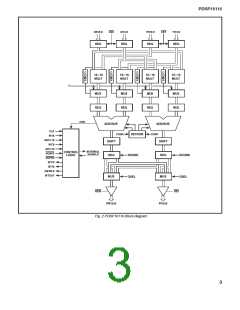
Shifter
Each of the two adder/subtractors are followed by shifters
controlled via the WTB control input. These shifters can each
apply two different shifts; however, the same shift is applied to
both real and imaginary components. The four shift options are:
1. WTB1:0 = 11 Shift complex product one place to the left, giving a shifter output format:
Bit Number
31 30 29 28 27 26 25
7
6
5
4
3
2
1
0
1
2
3
4
5
6
31
Weighting
S
2– 2– 2– 2– 2– 2–
2–24 2–25 2–26 2–27 2–28 2–29 2–30 2–
The effective weighting of the sign bit is 220
2. WTB1:0 = 00 No shift applied, giving a shifter output format:
Bit Number
Weighting
31 30 29 28 27 26
8
7
6
5
4
3
2
1
0
1
2
3
4
30
S
20 2– 2– 2– 2–
2–22 2–23 2–24 2–25 2–26 2–27 2–28 2–29 2–
The effective weighting of the sign bit is 221
3. WTB1:0 = 01 Shift complex product one place to the right, giving a shifter output format:
Bit Number
Weighting
31 30 29 28 27 26 25 24
6
5
4
3
2
1
0
1
2
3
4
5
29
S
21 20 2– 2– 2– 2– 2–
2–23 2–24 2–25 2–26 2–27 2–28 2–
The effective weighting of the sign bit is 222
4. WTB1:0 = 10 Shift complex product two places to the right, giving a shifter output format:
Bit Number
Weighting
31 30 29 28 27 26 25 24
6
5
4
3
2
1
0
1
2
3
4
28
S
22 21 20 2– 2– 2– 2–
2–22 2–23 2–24 2–25 2–26 2–27 2–
The effective weighting of the sign bit is 223
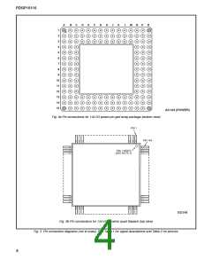
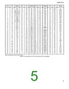
PIN DESCRIPTIONS
Overflow
If the left shift option is selected and the adder/subtractor
contains a 32-bit word, then an invalid result will be passed to
the output. An invalid output arising from this combination of
events will be flagged by the SFTA0 flag output. The SFTA0 flag
will go high if either the real or imaginary result is invalid.
XR, XI, YR, YI
Data inputs, 16 bits. Data is loaded into the input registers
from these ports on the rising edge of CLK. The data format is
fractional two’s complement, where the MSB (sign bit) is bit 15.
In normal mode the weighting of the MSB is 220 i.e. 21.
Output Select
PR, PI
The output from the shifters is passed to the output select
mux, which is controlled via the OSEL inputs. These inputs are
not registered and hence allow the output combination to be
changed within each cycle. The full complex 64-bit result from
the multiplier may therefore be output within a single cycle. The
OSEL control selects four different output combinations as
summarised in Table 4.
Data outputs, 16 bits. Data is clocked into the output regis-
ters and passed to the PR and PI outputs on the rising edge of
CLK. The data format is fractional two’s complement. The field
of the internal result selected for output via PR and PI is control-
led by signals OSEL1:0 (see Table 4).
CLK
OSEL0
PR
P1
Common clock to all internal registers
OSEL1
0
0
1
1
0
1
0
1
MSR
LSR
MSR
MSI
MSI
LSI
LSR
LSI
CEX, CEY
Clock enables for X and Y input ports. When low these inputs
enable the CLK signal to the X or Y input registers, allowing
new data to be clocked into the Multiplier.
Table 4 Output selection
CONX, CONY
Conjugate controls. If either of these inputs is high on the
rising edge of CLK, then the data on the associated input has its
imaginary component inverted (multiplied by 21), see Table 3.
CONX and CONY affect data input on the same clock rising
edge.
MSR and LSR are the most and least siginificant 16-bit words
of the real shifter output, MSl and LSl are the most and least
significant 16-bit words of the imaginary shifter output.
The output select options allow two different modes for ex-
tracting the full 32-bit result from the PDSP16116. The first mode
treats the two 16-bit outputs as real and imaginary ports, allow-
ing the real and imaginary results to be output in two halves on
the real and imaginary output ports. The second mode treats
the two 16-bit outputs as one 32-bit output and allows the real
and imaginary results to be output as 32-bit words.
ROUND
The ROUND control pin is used to round the most significant 16
bits of the output register. The ROUND input is not latched and is
intended to be tied high or low depending upon the application.
7

 MITEL [ MITEL NETWORKS CORPORATION ]