NJ88C50
Notes
1. Source impedance = 50W
2. Virtual earth input amplifier, therfore low impedance for small signals. Impedance is high once signal amplitude exceeds
typically ±0.125V.
3. Input amplifier may become unstable for higher values of Z .
S
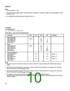
DYNAMIC
AC Characteristics
Vdd = 5V ± 10%, Tamb = -40 to +85°C
Input signals - Logic and current defining pins
Min
Max
Unit
Typ
Parameter
Condition
Data and strobe
Input voltage high
Input voltage low
Input capacitance
Input current
Vdd-0.8
0
Vdd
0.8
10
V
V
pF
µA
10
Clock
Vdd-0.8
0
Vdd
0.8
10
10
10
V
V
pF
µA
MHz
Input voltage high
Input voltage low
Input capacitance
Input current
Input frequency
Current setting pins
Input Signal RSA
Input current
Input Signal RSM
Input current
µA
µA
µA
80
32
Notes 1, 4
Notes 2, 4
Notes 3, 4
12.8
Input Signal RSC
Input current
Notes
1. The current set on pin RSA will be scaled up on chip by a factor of 3 to give the value of the auxiliary phase detector
output.
2. The current set on pin RSM will be scaled down on chip by a factor of 32 to provide the current I to the main phase
bo
detector which gives the outputs I
and I .
prop
int
3. The current set on pin RSC will be scaled down on chip by a factor of 128 to provide the current I to the main phase
co
detector which gives the outputs I
comp
and I .
comp 2
4. The voltage on each of the three current setting pins (RSA, RSM, RSC) is approximately 4V.
Therefore to give a typical current of 32µA on RSM for example, a 125kWresistor connected between the pin and GND
would be required.
10

 MITEL [ MITEL NETWORKS CORPORATION ]