Advance Information
MT91L60
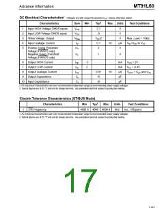
DC Electrical Characteristics† - Voltages are with respect to ground (VSS) unless otherwise stated.
‡
Characteristics
Sym
Min
Typ
Max
Units
Test Conditions
1
2
3
4
5
Input HIGH Voltage CMOS inputs
Input LOW Voltage CMOS inputs
VBias Voltage Output
VIHC
VILC
VBias
IIZ
2.1
.9
V
V
VDD/2
0.1
2
V
Max. Load = 10kΩ
Input Leakage Current
10
µA
V
VIN=VDD to VSS
Positive Going Threshold
Voltage (PWRST only)
Negative Going Threshold
Voltage (PWRST only)
VT+
VT-
1
V
6
7
8
9
Output HIGH Current
Output LOW Current
Output Leakage Current
Output Capacitance
IOH
IOL
IOZ
Co
Ci
- 2
2
mA
mA
µA
pF
VOH = 2V
VOL = 0.4V
0.01
15
10
VOUT = VDD and VSS
10 Input Capacitance
10
pF
† DC Electrical Characteristics are over recommended temperature range & recommended power supply voltages.
‡ Typical figures are at 25 °C and are for design aid only: not guaranteed and not subject to production testing.
Clockin Tolerance Characteristics (ST-BUS Mode)
‡
Characteristics
C4i Frequency
Min
Typ
Max
Units
Test Conditions
1
4095.6 4096 4096.4
kHz
(i.e., 100 ppm)
† AC Electrical Characteristics are over recommended temperature range & recommended power supply voltages.
‡ Typical figures are at 25 °C and are for design aid only: not guaranteed and not subject to production testing.
7-123

 MITEL [ MITEL NETWORKS CORPORATION ]