产品
最近搜索
热门搜索
发布采购


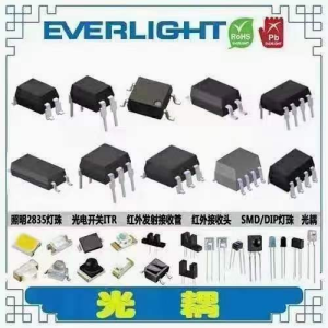
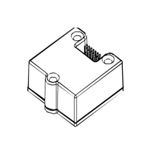
类别连接器,互连器件矩形连接器针座,插座,母插口制造商Samtec Inc.系列Tiger Eye™ SFM包装散装零件状态在售连接器类型插...
日期:4小时前
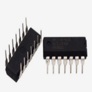
比较器是一种电子电路,其主要功能是将两个输入电压进行比较,并根据比较结果产生一个输出信号。这个输出信号通常是一个二进制逻辑电平(高电平或低电...
日期:8小时前
在电路中,电流源和电阻是基本的电子元件。电流源是提供固定电流的电子装置,而电阻则是限制电流通过的元件。在实际的电路中,常常会遇到需要将电流源...
日期:8小时前
磁致伸缩传感器(Magnetostrictive Sensor)是一种利用磁致伸缩效应测量物体长度、速度和加速度的传感器。该传感器主要由磁致...
日期:12小时前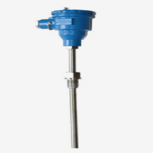
专业IC领域供求交易平台:提供全面的IC Datasheet资料和资讯,Datasheet 1000万数据,IC品牌1000多家。