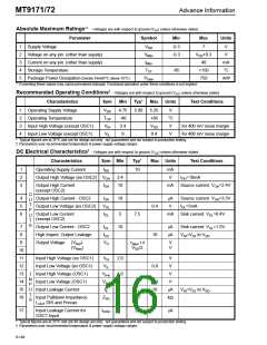
欢迎访问ic37.com |
会员登录 免费注册
发布采购

MT9171AN 参数 Datasheet PDF下载

MT9171AN图片预览
型号: MT9171AN
PDF下载: 下载PDF文件 查看货源
内容描述: ISO2 -CMOS ST- BUS⑩家庭数字用户接口电路数字网络接口电路 [ISO2-CMOS ST-BUS⑩ FAMILY Digital Subscriber Interface Circuit Digital Network Interface Circuit]
分类和应用: 网络接口电信集成电路光电二极管综合业务数字网
文件页数/大小: 22 页 / 396 K
品牌: MITEL [ MITEL NETWORKS CORPORATION ]
 浏览型号MT9171AN的Datasheet PDF文件第8页浏览型号MT9171AN的Datasheet PDF文件第9页浏览型号MT9171AN的Datasheet PDF文件第10页浏览型号MT9171AN的Datasheet PDF文件第11页浏览型号MT9171AN的Datasheet PDF文件第13页浏览型号MT9171AN的Datasheet PDF文件第14页浏览型号MT9171AN的Datasheet PDF文件第15页浏览型号MT9171AN的Datasheet PDF文件第16页  
MT9171/72
C-Channel
(Bit 0-7)
XXX01111
Internal Control
Register
00000000
Internal Diagnostic
Register
01000000
Advance Information
Description
Default Mode-1
Ž
: Bit rate is 80 kbit/s. ATTACK,
PSEN, DINB, DRR and all diagnostics are disabled.
TxHK=0.
XXX11111
00010000
Default Mode-2

Bit rate is 160 kbit/s. ATTACK,
PSEN, DINB, DRR and all diagnostics are disabled.
TxHK=0.
Table 4a. Default Mode Selection
01000000
Notes:
Ž
Default Mode 1 can also be selected by tying CDSTi/CDi pin low when DNIC is operating in dual mode.

Default Mode 2 can also be selected by tying CDSTi/CDi pin high when DNIC is operating in dual mode.
bit 0
Reg Sel-1
bit 1
Reg Sel-2
bit 2
Loopback
bit 3
bit 4
FUN
bit 5
PSWAP
bit 6
DLO
bit 7
Not Used
Default Mode Selection
(Refer to Table 4a)
Bit
0
1
2,3
Name
Reg Sel-1
Reg Sel-2
Loopback
Description
Register Select-1. Must be set to ’0’ to select the Diagnostic Register.
Register Select-2. Must be set to ’1’ to select the Diagnostic Register.
Bit 2
0
0
1
1
Bit 3
0
1
0
1
All loopback testing functions disabled. Normal operation.
DSTi internally looped back into DSTo for system diagnostics.
L
OUT
is internally looped back into L
IN
for system diagnostics.

DSTo is internally looped back into DSTi for end-to-end testing.
Ž
4
5
FUN
Œ
PSWAP
Œ
Force Unsync. When set to ’1’, the DNIC is forced out-of-sync to test the SYNC
recovery circuitry. When set to ’0’, the operation continues in synchronization.
Polynomial Swap. When set to ’1’, the scrambling and descrambling polynomials
are interchanged (use for MAS mode only). When set to ’0’, the polynomials retain
their normal designations.
Disable Line Out. When set to ’1’, the signal on L
OUT
is set set to V
Bias
. When set to
’0’, L
OUT
pin functions normally.
Must be set to ’0’ for normal operation.
Table 5. Diagnostic Register
6
7
DLO
Œ
Not Used
Notes:
Œ
When bits 4-7 of the Diagnostic Register are all set to one, the DNIC operates in one of the default modes as defined in Table 4a,
depending upon the status of bit-3.

Do not use L
OUT
to L
IN
loopback in DN/SLV mode.
Ž
Do not use DSTo to DSTi loopback in MOD/MAS mode.
selected. It continues to transfer the C-channel but
the D-channel and the HK bit no longer exist. DUAL
port operation must be used in MOD mode. The C-
channel is clocked in and out of the CD port by TCK
and CLD with TCK defining the bits and CLD the
channel boundaries of the data stream as shown in
Figure 8.
Line Port (L
IN
, L
OUT
)
The line interface is made up of L
OUT
and L
IN
with
L
OUT
driving the transmit signal onto the line and L
IN
receiving the composite transmit and receive signal
from the line. The line code used in the DNIC is
Biphase and is shown in Figure 10. The scrambled
NRZ data is differentially encoded meaning the
previous differential encoded output is XOR’d with
the current data bit which produces the current
output. This is then biphase encoded where
9-144