MT9076
Preliminary Information
20.2
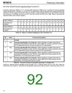
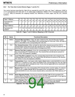
Per Time Slot Control Words (Pages 7 and 8) (T1)
The control functions described by Table 80 are repeated for each DS1 time slot. Page 7 addresses 10000 to
11111 correspond to DS1 time slot 1 to 16, while page 8 addresses 10000 to 10111 correspond to time slots
17 to 24. Table 83 illustrates the mapping between the addresses of these pages and the DS1 channel
numbers.
Page 7 Address:
0
1
1
2
2
3
3
4
4
5
5
6
6
7
7
8
8
9
9
10 11 12 13 14 15
Equivalent DS1
channel
10 11 12 13 14 15 16
Page 8 Address:
0
1
2
3
4
5
6
7
8
x
9
x
10 11 12 13 14 15
Equivalent DS1
channel
17 18 19 20 21 22 23 24
x
x
x
x
x
x
Table 82 - Pages 7 and 8 Address Mapping to DS1 Channels
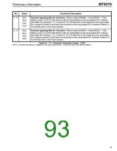
Functional Description
Bit
Name
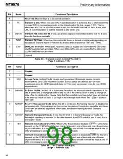
7
TXMSG Transmit Message Mode. If high, the data contained in the Transmit Message Register
(address 18H, page 1) is transmitted in the corresponding DS1 time slot. If zero, the data on
DSTi is transmitted on the corresponding DS1 time slot.
6
5
4
3
PCI
Per Channel Inversion. When set high the data for this channel sourced from DSTi is
inverted before being transmit onto the equivalent DS1 channel; the data received from the
incoming DS1 channel is inverted before it emerges from DSTo.
RTSL
LTSL
TTST
Remote Time Slot Loopback. If one, the corresponding DS1 receive time slot is looped to
the corresponding DS1 transmit time slot. This received time slot will also be present on
DSTo. If zero, the loopback is disabled.
Local Time Slot Loopback. If one, the corresponding transmit time slot is looped to the
corresponding receive time slot. This transmit time slot will also be present on the transmit
DS1 stream. If zero, this loopback is disabled.
Transmit Test. If one, a test signal, either digital milliwatt (when control bit ADSEQ is one) or
15
PRBS (2 -1) (ADSEQ is zero), will be transmitted in the corresponding DS1 time slot. More
than one time slot may be activated at once. If zero, the test signal will not be connected to
the corresponding time slot.
2
RTST
Receive Test. If one, the corresponding DSTo timeslot will be used for testing. If control bit
ADEQ is one, a digital milliwatt will be transmitted in the corresponding DSTo channel. If
control bit ADSEQ is zero, the receive channel will be connected to the PRBS detector (2 -
15
1).
1
0
RPSIG
CC
Serial Signaling Enable. If set low, the transmit signaling buffer for the equivalent DS1
channel will be sourced from the ST-BUS channel on CSTi associated with it. If set high the
transmit signaling RAM must be programmed via the microport.
Clear Channel. When set high no robbed bit signaling is inserted in the equivalent transmit
DS1 channel. When set low robbed bit signaling is included in every 6th channel.
Table 83 - Per Time Slot Control Words (Pages 7 and 8) (T1)
90

 MITEL [ MITEL NETWORKS CORPORATION ]