MT9076
Preliminary Information
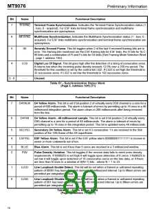
Bit
Name
Functional Description
7
TFSYNC Terminal Frame Synchronization. Indicates the Terminal Frame Synchronization status (1
- loss; 0 - acquired). For ESF links terminal frame synchronization and multiframe
synchronization are synonymous.
6
5
MFSYNC Multiframe Synchronization. Indicates the Multiframe Synchronization status (1 - loss; 0 -
acquired). For ESF links multiframe synchronization and terminal frame synchronization are
synonymous.
SE
LOS
- - -
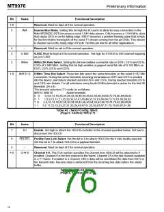
Severely Errored Frame. This bit toggles when 2 of the last 6 received framing bits are in
error. The framing bits monitored are the ESF framing bits for ESF links, the Ft bits for SLC-
96 links and a combination of Ft and Fs bits for D4 links (See Framing Mode Selection Word
- page 1 address 10H).
4
Digital Los Of Signal. This bit goes high after the detection of a string of consecutive zeros.
It returns low when the incoming pulse density exceeds 12.5% over a 250 ms period. The
threshold for this condition is set by the control bit L32Z. If L32Z is set high the threshold is
32 successive zeros. If L32Z is set low the threshold is 192 successive zeros.
3 - 0
Unused.
Table 51 - Synchronization Status Word
(Page 3, Address 10H) (T1)
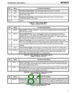
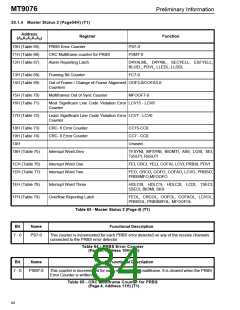
Bit
Name
Functional Description
7
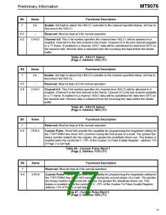
D4YALM D4 Yellow Alarm. This bit is set if bit position 2 of virtually every DS0 channel is a zero for a
period of 600 milliseconds. The alarm is tolerant of errors by permitting up to 16 ones in a 48
millisecond integration period. The alarm clears in 200 milliseconds after being removed
from the line.
6
D4Y48
D4 Yellow Alarm - 48 millisecond sample. This bit is set if bit position 2 of virtually every
DS0 channel is a zero for a period of 48 milliseconds. The alarm is tolerant of errors by
permitting up to 16 ones in the integration period. This bit is updated every 48 milliseconds.
5
4
SECYEL Secondary D4 Yellow Alarm. This bit is set if 2 consecutive ’1’s are received in the Sbit
position of the 12th frame of the D4 superframe.
ESFYEL
ESF Yellow Alarm. This bit is set if the ESF yellow alarm 0000000011111111 is receive in
seven or more codewords out of ten.
3
2
BLUE
PDV
Blue Alarm. This bit is set if less than 6 zeros are received in a 3 millisecond window.
Pulse Density Violation. This bit toggles if the receive data fails to meet ones density
requirements. If RXB8ZS is set high it will toggle upon detection of 8 zeros. I RxB8ZS is
set low it will toggle upon detection of 16 consecutive zeros on the line data, or if there
are less than N ones in a window of 8(N+1) bits - where N = 1 to 23.
1
0
LLED
LLDD
Line Loopback Enable Detect. This bit will be set when a framed or unframed repeating
pattern of 00001 has been detected during a 48 millisecond interval. Up to fifteen errors are
permitted per integration period.
Line Loopback Disable Detect. This bit will be set when a framed or unframed repeating
pattern of 001 has been detected during a 48 millisecond interval. Up to fifteen errors are
permitted per integration period.
Table 52 - Alarm Status Word
(Page 3, Address 11H) (T1)
76

 MITEL [ MITEL NETWORKS CORPORATION ]