MT9075A
Preliminary Information
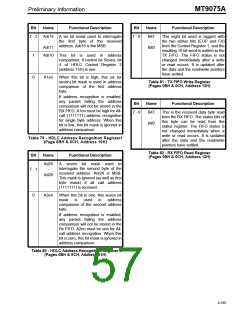
Bit
Name
Functional Description
Bit
Name
Functional Description
7
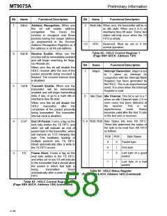
Adrec Address Recognition. When one
2
Mark-Idle When zero, the transmitter will be in
an idle state. When one it is in an
interframe time fill state. These two
states will only occur when the TX
FIFO is empty.
this bit will enable address
recognition.
This
forces
the
receiver to recognize only those
packets having the unique address
as programmed in the Receive
Address Recognition Registers or if
the address is an All call address.
1-0
RSV
Reserved: Must be set to 0 for
normal operation.
Table 83 - HDLC Control Register 1
(Page 0BH &0CH, Address 13H)
6
RxEN Receive Enable. When one the
receiver will be immediately enabled
and will begin searching for flags,
Go-Aheads etc.
Bit
Name
Functional Description
When zero this bit will disable the
HDLC receiver after the rest of the
packet presently being received is
finished. The receiver internal clock
is disabled.
7
Intgen
Interrupt Generation. Intgen is set
to
1
when an interrupt (in
conjunction with the Interrupt Mask
Register) has been generated by
the HDLC. This is an asynchronous
event. It is reset when the Interrupt
Register is read.
5
TxEN Transmit Enable. When one the
transmitter will be immediately
enabled and will begin transmitting
data, if any, or go to a mark idle or
interframe time fill state.
6
Idle Chan Idle Channel. This bit is set to a 1
when an idle Channel state (15 or
more ones) has been detected at
When zero this bit will disable the
the
receiver.
This
is
an
HDLC
transmitter
after
the
asynchronous
becomes valid after the first 15 bits
or the first zero is received.
event.
Status
completion of the packet presently
being transmitted. The transmitter
internal clock is disabled.
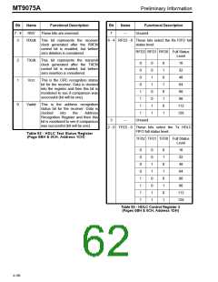
5, 4 RQ9, RQ8 Byte Status bits from RX FIFO.
These bits determine the status of
the byte to be read from RX FIFO
as follows:
4
EOP
End Of Packet. Forms a tag on the
next byte written the TX FIFO, and
when set will indicate an end of
packet byte to the transmitter, which
will transmit an FCS following this
byte. This facilitates loading of
multiple packets into TX FIFO.
Reset automatically after a write to
the TX FIFO occurs.
RQ9 RQ8
Byte Status
Packet byte.
0
0
1
0
1
0
First byte.
Last byte of a good
packet.
3
FA
Frame Abort. Forms a tag on the
next byte written to the TX FIFO,
and when set to one FA will indicate
to the transmitter that it should abort
the packet in which that byte is
1
1
Last byte of a bad
packet.
being
transmitted.
Reset
Table 84 - HDLC Status Register
(Pages 0BH & 0CH, Address 14H) (Continued)
automatically after a write to the TX
FIFO.
Table 83 - HDLC Control Register 1
(Page 0BH &0CH, Address 13H) (continued)
4-186

 MITEL [ MITEL NETWORKS CORPORATION ]