Preliminary Information
MT9075A
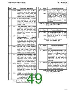
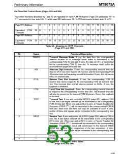
Per Time Slot Control Words (Pages 07H and 08H)
The control functions described by Table 69 are repeated for each PCM-30 channel. Page 07H addresses 10H to
1FH correspond to time slots 0 to 15, while page 08H addresses 10H to 1FH correspond to time slots 16 to 31.
Page 07H Address:
0
0
0
1
1
1
2
2
2
3
3
3
4
4
4
5
5
5
6
6
6
7
7
7
8
8
8
9
9
9
10 11 12 13 14 15
10 11 12 13 14 15
10 11 12 13 14 15
Equivalent PCM 30
Timeslots
Page 08H Address:
Equivalent PCM 30 16 17 18 19 20 21 22 23 24 25 26 27 28 29 30 31
Timeslots
Table 68 - Mapping to CEPT Channels
(Page 07H and 08H)
Bit
Name
Functional Description
7
TXMSG
Transmit Message Mode. If one, the data from the corresponding
address location of Tx message mode buffer is transmitted in the
corresponding PCM 30 time slot. If zero, the data on DSTi is transmitted
on the corresponding PCM 30 time slot. Tx message mode buffer are
accessed from pages 0FH and 10H.
6
5
4
3
ADI
Alternate Digit Inversion. If one, the corresponding transmit time slot
data on DSTi has every second bit inverted, and the corresponding PCM
30 receive time slot has every second bit inverted. If zero, this bit has no
effect on channel data.
RTSL
LTSL
TTST
Remote Time Slot Loopback. If one, the corresponding PCM 30
receive time slot is looped to the corresponding PCM 30 transmit time
slot. This received time slot will also be present on DSTo. If zero, the
loopback is disabled.
Local Time Slot Loopback. If one, the corresponding transmit time slot
is looped to the corresponding receive time slot. This transmit time slot
will also be present on the transmit PCM 30 stream. If zero, this loopback
is disabled.
Transmit Test. If one and control bit ADSEQ (page 02H, address 13H)
is one, the A-law digital milliwatt will be transmitted in the corresponding
PCM 30 time slot. When one and ADSEQ is zero, a Pseudo-Random Bit
15
Sequence (PRBS 2 -1) will be transmitted is the corresponding PCM 30
time slot. More than one time slot may be activated at once. If zero,
neither of these test signals will be connected to the corresponding time
slot.
2
RRST
Receive Test. If one and control bit ADSEQ (page 02H, address 13H) is
one, the A-law digital milliwatt will be transmitted in the corresponding
DSTo time slot. When one and ADSEQ is zero, a Pseudo Random Bit
15
Sequence (PRBS 2 -1) receiver will be connected to the corresponding
time slot. This receiver circuit will synchronize to the transmit PRBS
signal and perform a bit comparison of the two sequences. If zero,
neither of these test signals will be connected to the corresponding time
slot.
1
0
---
---
Unused.
Unused.
Table 69 - Per Time Slot Control Word
(Page 07H and 08H)
4-181

 MITEL [ MITEL NETWORKS CORPORATION ]