Preliminary Information
MT9075A
HDLC0 Functions
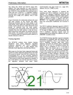
Opening
Data
Field
Closing
FCS
Two Bytes
Flag (7EH)
Flag (7EH)
When connected to the Data Link (DL) HDLC0 will
operate at a selected bit rate of 4, 8, 12, 16 or 20
kbits/sec. HDLC0 can be selected by setting the
control bit HDLC0 (bit 7) to one in page 01H, address
14H. When this bit is zero all interrupts from HDLC0
are masked. For more information refer to following
sections.
One Byte
01111110
n Bytes
n ≥ 2
One Byte
01111110
Table 9 - HDLC Frame Format
The data field usually consists of an address field,
control field and information field. The address field
consists of one or two bytes directly following the
opening flag. The control field consists of one byte
directly following the address field. The information
field immediately follows the control field and
consists of n bytes of data. The HDLC does not
distinguish between the control and information
fields and a packet does not need to contain an
information field to be valid.
HDLC1 Functions
This controller may be connected to time slot 16
under Common Channel Signalling (CCS) mode. It
should be noted that the AIS16S function (page 03H,
address 19H) will always be active and the TAIS16
function (page 01H, address 16H) will override all
other transmit signalling.
The FCS field, which precedes the closing flag,
consists of two bytes. A cyclic redundancy check
HDLC1 can be selected by setting the control bit
HDLC1 (bit 6) to one in page 01H, address 14H.
When this bit is zero all interrupts from HDLC1 are
masked.
utilizing
the
CCITT
standard
polynomial
16
12
5
“X +X +X +1” produces the 16-bit FCS. In the
transmitter the FCS is calculated on all bits of the
address and data field. The complement of the FCS
is transmitted, most significant bit first, in the FCS
field. The receiver calculates the FCS on the
incoming packet address, data and FCS field and
compares the result to “F0B8”. If no transmission
errors are detected and the packet between the flags
is at least 32 bits in length then the address and data
are entered into the receive FIFO minus the FCS
which is discarded.
HDLC Overview
The HDLC handles the bit oriented packetized data
transmission as per X.25 level two protocol defined
by CCITT. It provides flag and abort sequence
generation and detection, zero insertion and
deletion, and Frame Check Sequence (FCS)
generation and detection. A single byte, dual byte
and all call address in the received frame can be
recognized. Access to the receive FCS and inhibiting
of transmit FCS for terminal adaptation are also
provided. Each HDLC controller has a 128 byte deep
FIFO associated with it. The status and interrupt
flags are programmable for FIFO depths that can
vary from 16 to 128 bytes in steps of 16 bytes. These
and other features are enabled through the HDLC
control registers on page 0BH and 0CH.
Data Transparency (Zero Insertion/Deletion)
Transparency ensures that the contents of a data
packet do not imitate a flag, go-ahead, frame abort
or idle channel. The contents of a transmitted frame,
between the flags, is examined on a bit-by-bit basis
and a 0 is inserted after all sequences of 5
contiguous 1s (including the last five bits of the
FCS). Upon receiving five contiguous 1s within a
frame the receiver deletes the following 0.
HDLC Frame Structure
Invalid Frames
A valid HDLC frame (also referred as “packet”)
begins with an opening flag, contains at least 16 bits
of data field, and ends with a 16 bit FCS followed by
a closing flag (Table 9).
A frame is invalid if one of the following four
conditions exists:
•
If the FCS pattern generated from the
received data does not match the “F0B8”
pattern then the last data byte of the packet
is written to the received FIFO with a ‘bad
packet’ indication.
All HDLC frames start and end with a unique flag
sequence “01111110 ” (7EH). The transmitter
2
generates these flags and appends them to the
packet to be transmitted. The receiver searches the
incoming data stream for the flags on a bit-by-bit
basis to establish frame synchronization.
4-145

 MITEL [ MITEL NETWORKS CORPORATION ]