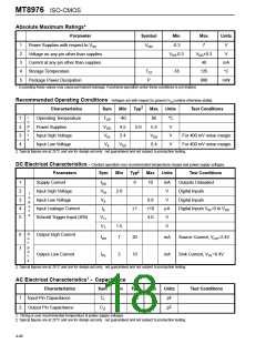
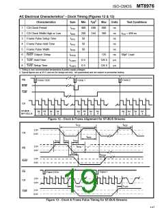
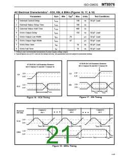
MT8976 ISO-CMOS
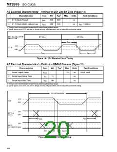
AC Electrical Characteristics† - DS1 Link Timing (Figures 19 & 20)
‡
Parameters
Sym
Min
Typ
Max
Units
Test Conditions
150 pF Load
1
2
3
4
5
6
7
8
Transmit Steering Delay
tTSD
tTST
50
150
30
ns
ns
ns
ns
ns
ns
ns
ns
Transmit Steering Transition Time
Received Steering Setup Time
Received Steering Hold Time
Received Data Setup Time
Received Data Hold Time
C1.5i Period
150 pF Load
tRSS
0
tRSH
tRDS
tRDH
tPC1.5
tWC1.5
30
-15
60
See Note 1
See Note 1
500
250
648
324
800
C1.5i Pulse Width High or Low
tPC1.5 = 648 ns
† Timing is over recommended temperature & power supply voltage ranges.
‡ Typical figures are at 25°C and are for design aid only; not guaranteed and not subject to production testing.
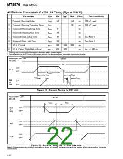
Transmitted DS1 Link
Bit Cells
Bit Cell
tPC1.5
2.0V
C1.5i
0.8V
tWC1.5
tTSD
t
TSD
tTST
tTST
TxA
or
TxB
2.4V
0.4V
Figure 19 - Transmit Timing for DS1 Link
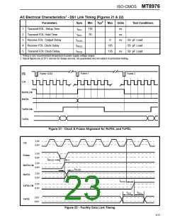
Received DS1 Link
Bit Cells
Bit Cell
t
t
RSH
RSS
2.0V
0.8V
RxA
or
RxB
2.0V
0.8V
RxD
t
tRDS
RDH
2.0V
0.8V
E1.5i
Figure 20 - Receive Timing for DS1 Link (see Note 1)
Note 1: The parameters tRDS and tRDH are related to device functionality. Network constraints may require tighter tolerances than the device
specifications.
4-50

 MITEL [ MITEL NETWORKS CORPORATION ]