SL1711
FUNCTIONAL DESCRIPTION
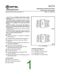
The SL1711 is a wideband quadrature downconverter,
optimised for application in both professional and consumer
digital satellite receiver systems and requiring a minimum
external component count. It contains all the elements
required for construction of a quadrature demodulator, with
the exception of tank circuit for the local oscillator.
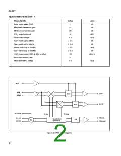
A block diagram is shown in Fig. 2.
The SL1711 oscillator can be used with either a varator
tuned tank circuit or with a SAW resonator. Both
configurations are described in the Application Notes section
of this Data Sheet.
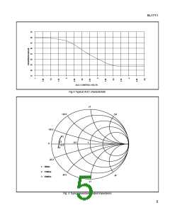
The mixer outputs are fed to balanced baseband AGC
amplifierstages,whichprovideforaminimumof16dBofAGC
control. The typical AGC characteristic is shown in Fig. 4.
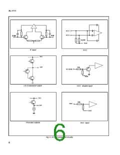
These amplifiers then feed a low output impedance true
differential to single-ended converter output stage. In normal
application the output can be either directly AC coupled to the
ADC converter such as the VP216, which will generally have
a high input impedance, or to drive an anti alias filter. In this
later case the maximum load presented to the SL1711 must
not exceed a parallel combination of 1KΩ and 20pF. The
typical baseband output impedance is contained in Fig. 5.
It is recommended that the device is operated with an
output amplitude of 760mV under lock conditions.
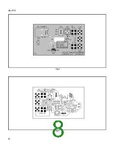
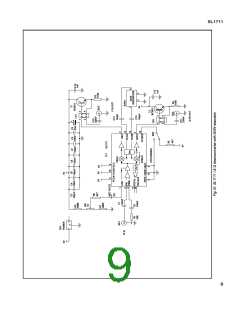
A typical digital satellite tuner application from tuner input
to data transport stream is shown in Fig. 13
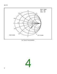
In normal application the second satellite IF frequency of
typically 402.75 or 479.5 MHz is fed from the tuner SAW filter
to the RF preamplifier, which is optimised for impedance
match and signal handling. The amplifier output signal is then
split into two balanced channels to drive the In-phase and
Quadrature mixers. The typical RF input impedance is shown
in Fig. 3
In-phase and Quadrature LO signals for the mixers are
derived from the on board local oscillator, which uses an
external varactor tuned resonant network and is optimised for
low phase noise. The VCO also drives an on board divide by
32prescalerwhoseoutputscanbeusedfordrivinganexternal
PLL control loop for the VCO, where the PLL loop is contained
within the QPSK demodulator, for example the VP305. For
optimum performance in the varactor tuned application the
VCOshouldbefullysymmetric. TheVCOhasadisablefacility
by grounding pin 15, VCODIS; in normal applications this pin
is pulled to Vcc via a 4K7 resistor.
Under transient conditions the output should not exceed
the clipping voltage.
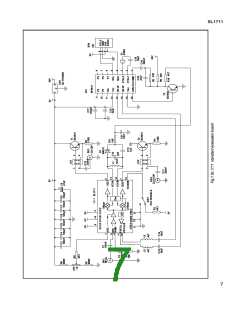
Input and output interface circuitry is contained in Fig. 6.
Thetypicalkeyperformancefiguresat480MHzIF,5VVcc,
1kΩ loadand25degCambientarecontainedintableheaded
'QUICK REFERENCE DATA'. With SAWR oscillator
application the gain and phase match performance will
typically exceed these numbers.
3

 MITEL [ MITEL NETWORKS CORPORATION ]