PIC18F2220/2320/4220/4320
16.4.7
SETUP FOR PWM OPERATION
16.4.8
OPERATION IN POWER MANAGED
MODES
The following steps should be taken when configuring
the ECCP1 module for PWM operation:
In Sleep mode, all clock sources are disabled. Timer2
will not increment and the state of the module will not
change. If the ECCP pin is driving a value, it will con-
tinue to drive that value. When the device wakes up, it
will continue from this state. If Two-Speed Start-ups are
enabled, the initial start-up frequency from INTOSC
and the postscaler may not be stable immediately.
1. Configure the PWM pins P1A and P1B (and
P1C and P1D, if used) as inputs by setting the
corresponding TRISC and TRISD bits.
2. Set the PWM period by loading the PR2 register.
3. Configure the ECCP module for the desired
PWM mode and configuration by loading the
CCP1CON register with the appropriate values:
In PRI_IDLE mode, the primary clock will continue to
clock the ECCP module without change.
• Select one of the available output
configurations and direction with the
P1M1:P1M0 bits.
In all other power managed modes, the selected power
managed mode clock will clock Timer2. Other power
managed mode clocks will most likely be different than
the primary clock frequency.
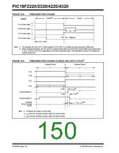
• Select the polarities of the PWM output
signals with the CCP1M3:CCP1M0 bits.
4. Set the PWM duty cycle by loading the CCPR1L
register and CCP1CON<5:4> bits.
16.4.8.1
OPERATION WITH FAIL-SAFE
CLOCK MONITOR
5. For Half-Bridge Output mode, set the dead band
delay by loading PWM1CON<6:0> with the
appropriate value.
If the Fail-Safe Clock Monitor is enabled
(CONFIG1H<6> is programmed), a clock failure will
force the device into the RC_RUN Power Managed
mode and the OSCFIF bit (PIR2<7>) will be set. The
ECCP will then be clocked from the internal oscillator
clock source which may have a different clock
frequency than the primary clock. By loading the
IRCF2:IRCF0 bits on Resets, the user can obtain a
frequency higher than the default INTRC clock source
in the event of a clock failure.
6. If auto-shutdown operation is required, load the
ECCPAS register:
• Select the auto-shutdown sources using the
ECCPAS<2:0> bits.
• Select the shutdown states of the PWM
output pins using PSSAC1:PSSAC0 and
PSSBD1:PSSBD0 bits.
• Set the ECCPASE bit (ECCPAS<7>).
See the previous section for additional details.
• Configure the comparators using the CMCON
register.
16.4.9
EFFECTS OF A RESET
• Configure the comparator inputs as analog
inputs.
Both Power-on and subsequent Resets will force all
ports to Input mode and the CCP registers to their
Reset states.
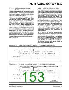
7. If auto-restart operation is required, set the
PRSEN bit (PWM1CON<7>).
This forces the Enhanced CCP module to reset to a
state compatible with the standard CCP module.
8. Configure and start TMR2:
• Clear the TMR2 interrupt flag bit by clearing
the TMR2IF bit (PIR1<1>).
• Set the TMR2 prescale value by loading the
T2CKPS bits (T2CON<1:0>).
• Enable Timer2 by setting the TMR2ON bit
(T2CON<2>).
9. Enable PWM outputs after a new PWM cycle
has started:
• Wait until TMR2 overflows (TMR2IF bit is set).
• Enable the CCP1/P1A, P1B, P1C and/or P1D
pin outputs by clearing the respective TRISC
and TRISD bits.
• Clear the ECCPASE bit (ECCPAS<7>).
DS39599C-page 152
2003 Microchip Technology Inc.

 MICROCHIP [ MICROCHIP ]