PIC17C4X
Design considerations
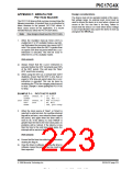
APPENDIX F: ERRATA FOR
PIC17C42 SILICON
The PIC17C42 devices that you have received have the
following anomalies. At present there is no intention for
future revisions to the present PIC17C42 silicon. If
these cause issues for the application, it is recom-
mended that you select the PIC17C42A device.
The device must not be operated outside of the speci-
fied voltage range. An external reset circuit must be
used to ensure the device is in reset when a brown-out
occurs or the VDD rise time is too long. Failure to
ensure that the device is in reset when device voltage
is out of specification may cause the device to lock-up
and ignore the MCLR pin.
Note: New designs should use the PIC17C42A.
1. When the Oscillator Start-Up Timer (OST) is
enabled (in LF or XT oscillator modes), any inter-
rupt that wakes the processor may cause a WDT
reset.This occurs when the WDT is greater than
or equal to 50% time-out period when theSLEEP
instruction is executed. This will not occur in
either the EC or RC oscillator modes.
Work-arounds
a) Always ensure that the CLRWDT instruction is
executed before the WDT increments past 50%
of the WDT period. This will keep the “false”
WDT reset from occurring.
b) When using the WDT as a normal timer (WDT
disabled), ensure that the WDT is less than or
equal to 50% time-out period when the SLEEP
instruction is executed. This can be done by
monitoring the TO bit for changing state from set
to clear. Example 1 shows putting the PIC17C42
to sleep.
EXAMPLE F-1: PIC17C42 TO SLEEP
BTFSS
CLRWDT
LOOP BTFSC
GOTO
CPUSTA, TO ; TO = 0?
; YES, WDT = 0
CPUSTA, TO ; WDT rollover?
LOOP
; NO, Wait
SLEEP
; YES, goto Sleep
2. When the clock source of Timer1 or Timer2 is
selected to external clock, the overflow interrupt
flag will be set twice, once when the timer equals
the period, and again when the timer value is
reset to 0h. If the latency to clear TMRxIF is
greater than the time to the next clock pulse, no
problems will be noticed. If the latency is less
than the time to the next timer clock pulse, the
interrupt will be serviced twice.
Work-arounds
a) Ensure that the timer has rolled over to 0h before
clearing the flag bit.
b) Clear the timer in software. Clearing the timer in
software causes the period to be one count less
than expected.
1996 Microchip Technology Inc.
DS30412C-page 223
This document was created with FrameMaker 4 0 4

 MICROCHIP [ MICROCHIP ]