PIC17C75X
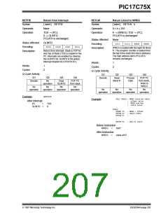
RETFIE
Return from Interrupt
[ label ] RETFIE
None
RETLW
Return Literal to WREG
[ label ] RETLW k
0 ≤ k ≤ 255
Syntax:
Syntax:
Operands:
Operation:
Operands:
Operation:
TOS → (PC);
k → (WREG); TOS → (PC);
0 → GLINTD;
PCLATH is unchanged
PCLATH is unchanged.
Status Affected:
Encoding:
None
Status Affected:
Encoding:
GLINTD
1011
0110
kkkk
kkkk
0000
0000
0000
0101
WREG is loaded with the eight bit literal
'k'. The program counter is loaded from
the top of the stack (the return address).
The high address latch (PCLATH)
remains unchanged.
Description:
Return from Interrupt. Stack is POP’ed
and Top of Stack (TOS) is loaded in the
PC. Interrupts are enabled by clearing
the GLINTD bit. GLINTD is the global
interrupt disable bit (CPUSTA<4>).
Description:
Words:
Cycles:
1
2
Words:
Cycles:
1
2
Q Cycle Activity:
Q1
Q Cycle Activity:
Q1
Q2
Q3
Q4
Q2
Q3
Q4
Decode
Read
Process
Data
POP PC
from stack,
Write to
literal 'k'
Decode
No
operation
Clear
GLINTD
POP PC
from stack
WREG
No
No
No
No
No
No
No
No
operation
operation
operation
operation
operation
operation
operation
operation
RETFIE
Example:
CALL TABLE ; WREG contains table
Example:
After Interrupt
;
;
;
offset value
WREG now has
table value
PC
GLINTD
=
=
TOS
0
:
TABLE
ADDWF PC
; WREG = offset
; Begin table
;
RETLW k0
RETLW k1
:
:
RETLW kn
; End of table
Before Instruction
WREG
=
0x07
After Instruction
WREG
=
value of k7
1997 Microchip Technology Inc.
DS30264A-page 207

 MICROCHIP [ MICROCHIP ]