PIC16F913/914/916/917/946
Even if the flag bits were checked before executing a
SLEEP instruction, it may be possible for flag bits to
become set before the SLEEPinstruction completes. To
determine whether a SLEEPinstruction executed, test
the PD bit. If the PD bit is set, the SLEEP instruction
was executed as a NOP.
To ensure that the WDT is cleared, a CLRWDTinstruction
should be executed before a SLEEPinstruction.
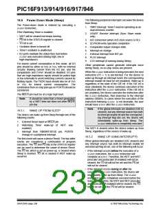
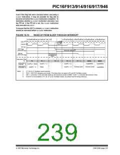
FIGURE 16-10:
WAKE-UP FROM SLEEP THROUGH INTERRUPT
Q1 Q2 Q3 Q4 Q1 Q2 Q3 Q4 Q1
Q1 Q2 Q3 Q4 Q1 Q2 Q3 Q4 Q1 Q2 Q3 Q4 Q1 Q2 Q3 Q4
OSC1(1)
CLKOUT(4)
INT pin
(2)
TOST
INTF flag
(INTCON reg.)
Interrupt Latency(3)
GIE bit
(INTCON reg.)
Processor in
Sleep
Instruction Flow
PC
PC
PC + 1
PC + 2
PC + 2
PC + 2
0004h
0005h
Instruction
Fetched
Inst(0004h)
Inst(PC + 1)
Inst(PC + 2)
Inst(0005h)
Inst(PC) = Sleep
Instruction
Executed
Dummy Cycle
Dummy Cycle
Sleep
Inst(PC + 1)
Inst(PC - 1)
Inst(0004h)
Note 1:
XT, HS or LP Oscillator mode assumed.
TOST = 1024 TOSC (drawing not to scale). This delay does not apply to EC and RC Oscillator modes.
GIE = 1assumed. In this case after wake-up, the processor jumps to 0004h. If GIE = 0, execution will continue in-line.
2:
3:
4:
CLKOUT is not available in XT, HS, LP or EC Oscillator modes, but shown here for timing reference.
© 2007 Microchip Technology Inc.
DS41250F-page 237

 MICROCHIP [ MICROCHIP ]