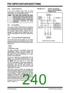
PIC16F913/914/916/917/946
The following peripheral interrupts can wake the device
from Sleep:
16.5 Power-Down Mode (Sleep)
The Power-down mode is entered by executing a
SLEEPinstruction.
1. TMR1 Interrupt. Timer1 must be operating as an
asynchronous counter.
If the Watchdog Timer is enabled:
2. USART Receive Interrupt (Sync Slave mode
only)
• WDT will be cleared but keeps running.
• PD bit in the STATUS register is cleared.
• TO bit is set.
3. A/D conversion (when A/D clock source is RC)
4. EEPROM write operation completion
5. Comparator output changes state
6. Interrupt-on-change
• Oscillator driver is turned off.
• Timer1 oscillator is unaffected
• I/O ports maintain the status they had before
SLEEPwas executed (driving high, low or
high-impedance).
7. External Interrupt from INT pin
8. PLVD Interrupt
9. LCD Interrupt (if running during Sleep)
For lowest current consumption in this mode, all I/O
pins should be either at VDD or VSS, with no external
circuitry drawing current from the I/O pin, and the
comparators and CVREF should be disabled. I/O pins
that are high-impedance inputs should be pulled high
or low externally to avoid switching currents caused by
floating inputs. The T0CKI input should also be at VDD
or VSS for lowest current consumption. The
contribution from on-chip pull-ups on PORTB should be
considered.
Other peripherals cannot generate interrupts since
during Sleep, no on-chip clocks are present.
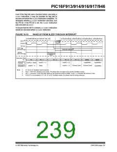
When the SLEEPinstruction is being executed, the next
instruction (PC + 1) is pre-fetched. For the device to
wake-up through an interrupt event, the corresponding
interrupt enable bit must be set (enabled). Wake-up is
regardless of the state of the GIE bit. If the GIE bit is
clear (disabled), the device continues execution at the
instruction after the SLEEPinstruction. If the GIE bit is
set (enabled), the device executes the instruction after
the SLEEP instruction, then branches to the interrupt
address (0004h). In cases where the execution of the
instruction following SLEEP is not desirable, the user
should have a NOPafter the SLEEPinstruction.
The MCLR pin must be at a logic high level.
Note:
It should be noted that a Reset generated
by a WDT time-out does not drive MCLR
pin low.
Note:
If the global interrupts are disabled (GIE is
cleared), but any interrupt source has both
its interrupt enable bit and the correspond-
ing interrupt flag bits set, the device will
immediately wake-up from Sleep. The
SLEEPinstruction is completely executed.
16.5.1
WAKE-UP FROM SLEEP
The device can wake-up from Sleep through one of the
following events:
1. External Reset input on MCLR pin.
2. Watchdog Timer wake-up (if WDT was
enabled).
The WDT is cleared when the device wakes up from
Sleep, regardless of the source of wake-up.
3. Interrupt from RB0/INT/SEG0 pin, PORTB
change or a peripheral interrupt.
16.5.2
WAKE-UP USING INTERRUPTS
The first event will cause a device Reset. The two latter
events are considered a continuation of program
execution. The TO and PD bits in the STATUS register
can be used to determine the cause of device Reset.
The PD bit, which is set on power-up, is cleared when
Sleep is invoked. TO bit is cleared if WDT wake-up
occurred.
When global interrupts are disabled (GIE cleared) and
any interrupt source has both its interrupt enable bit
and interrupt flag bit set, one of the following will occur:
• If the interrupt occurs before the execution of a
SLEEPinstruction, the SLEEPinstruction will
complete as a NOP. Therefore, the WDT and WDT
prescaler and postscaler (if enabled) will not be
cleared, the TO bit will not be set and the PD bit
will not be cleared.
• If the interrupt occurs during or after the
execution of a SLEEPinstruction, the device will
immediately wake-up from Sleep. The SLEEP
instruction will be completely executed before the
wake-up. Therefore, the WDT and WDT prescaler
and postscaler (if enabled) will be cleared, the TO
bit will be set and the PD bit will be cleared.
DS41250F-page 236
© 2007 Microchip Technology Inc.

 MICROCHIP [ MICROCHIP ]