PIC16F913/914/916/917/946
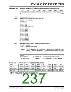
REGISTER 16-2: WDTCON – WATCHDOG TIMER CONTROL REGISTER (ADDRESS: 105h)
U-0
—
U-0
—
U-0
—
R/W-0
R/W-1
R/W-0
R/W-0
R/W-0
WDTPS3 WDTPS2 WDTPS1 WDTPS0 SWDTEN
bit 0
bit 7
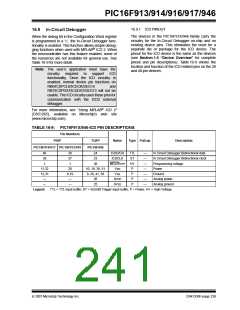
bit 7-5
bit 4-1
Unimplemented: Read as ‘0’
WDTPS<3:0>: Watchdog Timer Period Select bits
Bit Value = Prescale Rate
0000 = 1:32
0001 = 1:64
0010 = 1:128
0011 = 1:256
0100 = 1:512 (Reset value)
0101 = 1:1024
0110 = 1:2048
0111 = 1:4096
1000 = 1:8192
1001 = 1:16384
1010 = 1:32768
1011 = 1:65536
1100 = reserved
1101 = reserved
1110 = reserved
1111 = reserved
bit 0
SWDTEN: Software Enable or Disable the Watchdog Timer bit(1)
1= WDT is turned on
0= WDT is turned off (Reset value)
Note 1: If WDTE Configuration bit = 1, then WDT is always enabled, irrespective of this
control bit. If WDTE Configuration bit = 0, then it is possible to turn WDT on/off with
this control bit.
Legend:
R = Readable bit
W = Writable bit
‘1’ = Bit is set
U = Unimplemented bit, read as ‘0’
‘0’ = Bit is cleared x = Bit is unknown
- n = Value at POR
TABLE 16-8: SUMMARY OF WATCHDOG TIMER REGISTERS
Name
Bit 7
Bit 6
Bit 5
Bit 4
Bit 3
Bit 2
Bit 1
Bit 0
CONFIG
CPD
RBPU
—
CP
INTEDG
—
MCLRE
T0CS
—
PWRTE
T0SE
WDTE
PSA
FOSC2
PS2
FOSC1
PS1
FOSC0
PS0
OPTION_REG
WDTCON
WDTPS3 WDTPS2 WSTPS1 WDTPS0 SWDTEN
Legend: Shaded cells are not used by the Watchdog Timer.
Note 1: See Register 16-1 for operation of all Configuration Word register bits.
© 2007 Microchip Technology Inc.
DS41250F-page 235

 MICROCHIP [ MICROCHIP ]