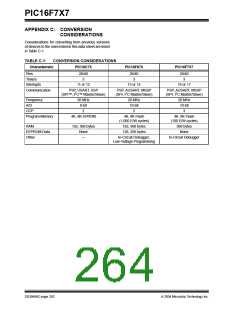
PIC16F7X7
CLRW .......................................................................196
CLRWDT...................................................................196
COMF .......................................................................196
DECF ........................................................................196
DECFSZ....................................................................197
Firmware Instructions................................................193
General Format.........................................................193
GOTO .......................................................................197
INCF..........................................................................197
INCFSZ.....................................................................197
IORLW ......................................................................197
IORWF ......................................................................197
MOVF........................................................................198
MOVLW ....................................................................198
MOVWF ....................................................................198
NOP ..........................................................................198
Opcode Field Descriptions........................................193
Read-Modify-Write Operations .................................193
RETFIE .....................................................................198
RETLW .....................................................................198
RETURN ...................................................................199
RLF ...........................................................................199
RRF...........................................................................199
SLEEP ......................................................................199
SUBLW .....................................................................199
SUBWF.....................................................................199
SWAPF .....................................................................200
XORLW.....................................................................200
XORWF.....................................................................200
Summary Table.........................................................194
INT Interrupt (RB0/INT). See Interrupt Sources.
L
Load Conditions................................................................ 222
Loading of PC..................................................................... 29
Low-Voltage Detect .......................................................... 174
Characteristics.......................................................... 221
Effects of a Reset ..................................................... 178
Operation.................................................................. 177
Current Consumption ....................................... 178
Reference Voltage Set Point ............................ 178
Operation During Sleep ............................................ 178
Time-out Sequence .................................................. 178
Low-Voltage Detect (LVD)................................................ 169
LVD. See Low-Voltage Detect.
M
Master Clear (MCLR)
MCLR Reset, Normal Operation............... 172, 179, 180
MCLR Reset, Sleep.................................. 172, 179, 180
Master Synchronous Serial Port (MSSP).
See MSSP.
Master Synchronous Serial Port. See MSSP
MCLR/VPP/RE3 Pin .............................................................. 8
MCLR/VPP/RE3 Pin ............................................................ 11
Memory Organization ......................................................... 15
Data Memory .............................................................. 15
Program Memory........................................................ 15
Program Memory and Stack Maps ............................. 15
MPLAB ASM30 Assembler, Linker, Librarian................... 202
MPLAB ICD 2 In-Circuit Debugger ................................... 203
MPLAB ICE 2000 High-Performance
Universal In-Circuit Emulator.................................... 203
MPLAB ICE 4000 High-Performance
INTCON Register
GIE Bit.........................................................................23
INT0IE Bit....................................................................23
INT0IF Bit....................................................................23
PEIE Bit.......................................................................23
RBIF Bit................................................................. 23, 56
TMR0IE Bit..................................................................23
Universal In-Circuit Emulator.................................... 203
MPLAB Integrated Development
Environment Software .............................................. 201
MPLAB PM3 Device Programmer .................................... 203
MPLINK Object Linker/MPLIB Object Librarian................ 202
MSSP.................................................................................. 93
2
2
2
Inter-Integrated Circuit. See I C.
I C Mode. See I C.
SPI Mode. See SPI.
Internal Oscillator Block ......................................................35
INTRC Modes .............................................................36
Interrupt Sources....................................................... 169, 184
A/D Conversion Complete ........................................155
Interrupt-on-Change (RB7:RB4) .................................56
RB0/INT Pin, External...............................................185
TMR0 Overflow .........................................................185
Interrupts
MSSP Module
Control Registers (General)........................................ 93
Overview..................................................................... 93
Multi-Master Mode............................................................ 127
O
OPTION_REG Register
Exiting Sleep with........................................................48
Synchronous Serial Port Interrupt...............................25
Interrupts, Context Saving During.....................................185
Interrupts, Enable Bits
INTEDG Bit................................................................. 22
PS2:PS0 Bits.............................................................. 22
PSA Bit ....................................................................... 22
RBPU Bit .................................................................... 22
T0CS Bit ..................................................................... 22
T0SE Bit ..................................................................... 22
OSC1/CLKI/RA7 Pin....................................................... 8, 11
OSC2/CLKO/RA6 Pin..................................................... 8, 11
Oscillator Configuration ...................................................... 33
ECIO........................................................................... 33
EXTRC ..................................................................... 179
HS....................................................................... 33, 179
INTIO1 ........................................................................ 33
INTIO2 ........................................................................ 33
INTRC....................................................................... 179
LP ....................................................................... 33, 179
RC ........................................................................ 33, 35
RCIO........................................................................... 33
XT ....................................................................... 33, 179
Global Interrupt Enable (GIE Bit) ........................23, 184
Interrupt-on-Change (RB7:RB4)
Enable (RBIE Bit)..............................................185
Peripheral Interrupt Enable (PEIE Bit) ........................23
RB0/INT Enable (INT0IE Bit) ......................................23
TMR0 Overflow Enable (TMR0IE Bit).........................23
Interrupts, Flag Bits
Interrupt-on Change (RB7:RB4)
Flag (RBIF Bit) ....................................................23
Interrupt-on-Change (RB7:RB4)
Flag (RBIF Bit) ...................................... 23, 56, 185
RB0/INT Flag (INT0IF Bit)...........................................23
TMR0 Overflow Flag (TMR0IF Bit) ...........................185
INTRC Modes
Adjustment..................................................................36
DS30498C-page 266
2004 Microchip Technology Inc.

 MICROCHIP [ MICROCHIP ]