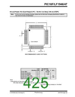
PIC16F/LF1946/47
INDEX
EUSART Receive..................................................... 290
EUSART Transmit.................................................... 289
External RC Mode ...................................................... 62
Fail-Safe Clock Monitor (FSCM)................................. 70
Generic I/O Port........................................................ 121
Interrupt Logic............................................................. 83
LCD Bias Voltage Generation .................................. 335
LCD Clock Generation.............................................. 334
On-Chip Reset Circuit................................................. 75
Peripheral Interrupt Logic ........................................... 84
PIC16F/LF1946/47 ............................................... 10, 18
PWM (Enhanced) ..................................................... 216
Resonator Operation .................................................. 61
Timer0 ...................................................................... 187
Timer1 ...................................................................... 191
Timer1 Gate.............................................. 196, 197, 198
Timer2/4/6 ................................................................ 203
Voltage Reference.................................................... 151
Voltage Reference Output Buffer Example .............. 170
BORCON Register.............................................................. 77
BRA .................................................................................. 372
Break Character (12-bit) Transmit and Receive ............... 308
Brown-out Reset (BOR)...................................................... 77
Specifications ........................................................... 401
Timing and Characteristics....................................... 400
A
A/D
Specifications............................................................ 403
Absolute Maximum Ratings (PIC16F/LF1946/47) ............ 381
AC Characteristics
Industrial and Extended ............................................ 396
Load Conditions........................................................ 395
ACKSTAT ......................................................................... 270
ACKSTAT Status Flag ...................................................... 270
ADC .................................................................................. 153
Acquisition Requirements ......................................... 163
Associated registers.................................................. 165
Block Diagram........................................................... 153
Calculating Acquisition Time..................................... 163
Channel Selection..................................................... 154
Configuration............................................................. 154
Configuring Interrupt ................................................. 158
Conversion Clock...................................................... 154
Conversion Procedure .............................................. 158
Internal Sampling Switch (RSS) Impedance.............. 163
Interrupts................................................................... 156
Operation .................................................................. 157
Operation During Sleep ............................................ 157
Port Configuration..................................................... 154
Reference Voltage (VREF)......................................... 154
Source Impedance.................................................... 163
Special Event Trigger................................................ 157
Starting an A/D Conversion ...................................... 156
ADCON0 Register....................................................... 32, 159
ADCON1 Register....................................................... 32, 160
ADDFSR ........................................................................... 371
ADDWFC .......................................................................... 371
ADRESH Register............................................................... 32
ADRESH Register (ADFM = 0)......................................... 161
ADRESH Register (ADFM = 1)......................................... 162
ADRESL Register (ADFM = 0).......................................... 161
ADRESL Register (ADFM = 1).......................................... 162
Alternate Pin Function....................................................... 121
Analog-to-Digital Converter. See ADC
C
C Compilers
MPLAB C18.............................................................. 416
MPLAB C30.............................................................. 416
CALL................................................................................. 373
CALLW ............................................................................. 373
Capacitive Sensing........................................................... 317
Associated registers w/ Capacitive Sensing............. 325
Specifications ........................................................... 412
Capture Module. See Enhanced Capture/Compare/
PWM(ECCP)
Capture/Compare/PWM ................................................... 207
Capture/Compare/PWM (CCP)
Associated Registers w/ Capture ............................. 209
Associated Registers w/ Compare ........................... 211
Associated Registers w/ PWM ......................... 215, 228
Capture Mode........................................................... 208
CCPx Pin Configuration............................................ 208
Compare Mode......................................................... 210
CCPx Pin Configuration.................................... 210
Software Interrupt Mode........................... 208, 210
Special Event Trigger....................................... 210
Timer1 Mode Resource............................ 208, 210
Prescaler .................................................................. 208
PWM Mode
ANSELA Register ............................................................. 125
ANSELE Register ............................................................. 137
ANSELF Register.............................................................. 141
APFCON Register............................................................. 122
Assembler
MPASM Assembler................................................... 416
B
BAUDCON Register.......................................................... 300
BF ............................................................................. 270, 272
BF Status Flag .......................................................... 270, 272
Block Diagram
Capacitive Sensing ........................................... 317, 318
Block Diagrams
Duty Cycle ........................................................ 213
Effects of Reset................................................ 215
Example PWM Frequencies and
(CCP) Capture Mode Operation ............................... 208
ADC .......................................................................... 153
ADC Transfer Function ............................................. 164
Analog Input Model........................................... 164, 177
CCP PWM................................................................. 212
Clock Source............................................................... 59
Comparator............................................................... 174
Compare Mode Operation ........................................ 210
Crystal Operation.................................................. 61, 62
Digital-to-Analog Converter (DAC)............................ 169
Resolutions, 20 MHZ................................ 214
Example PWM Frequencies and
Resolutions, 32 MHZ................................ 214
Example PWM Frequencies and
Resolutions, 8 MHz .................................. 214
Operation in Sleep Mode.................................. 215
Resolution ........................................................ 214
System Clock Frequency Changes .................. 215
PWM Operation........................................................ 212
PWM Overview......................................................... 212
2010 Microchip Technology Inc.
Preliminary
DS41414A-page 427

 MICROCHIP [ MICROCHIP ]