PIC16F/LF1946/47
10.1 Independent Clock Source
10.3 Time-Out Period
The WDT derives its time base from the 31 kHz
LFINTOSC internal oscillator.
The WDTPS bits of the WDTCON register set the
time-out period from 1 ms to 256 seconds. After a
Reset, the default time-out period is 2 seconds.
10.2 WDT Operating Modes
10.4 Clearing the WDT
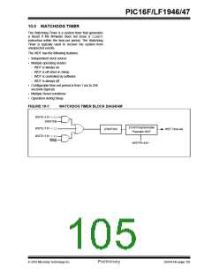
The Watchdog Timer module has four operating modes
controlled by the WDTE<1:0> bits in Configuration
Word 1. See Table 10-1.
The WDT is cleared when any of the following condi-
tions occur:
• Any Reset
10.2.1
WDT IS ALWAYS ON
• CLRWDTinstruction is executed
• Device enters Sleep
When the WDTE bits of Configuration Word 1 are set to
‘11’, the WDT is always on.
• Device wakes up from Sleep
• Oscillator fail event
WDT protection is active during Sleep.
• WDT is disabled
10.2.2
WDT IS OFF IN SLEEP
• Oscillator Start-up TImer (OST) is running
When the WDTE bits of Configuration Word 1 are set to
See Table 10-2 for more information.
‘10’, the WDT is on, except in Sleep.
WDT protection is not active during Sleep.
10.5 Operation During Sleep
10.2.3
WDT CONTROLLED BY SOFTWARE
When the device enters Sleep, the WDT is cleared. If
the WDT is enabled during Sleep, the WDT resumes
counting.
When the WDTE bits of Configuration Word 1 are set to
‘01’, the WDT is controlled by the SWDTEN bit of the
WDTCON register.
When the device exits Sleep, the WDT is cleared
again. The WDT remains clear until the OST, if
enabled, completes. See Section 5.0 “Oscillator
Module (With Fail-Safe Clock Monitor)” for more
information on the OST.
WDT protection is unchanged by Sleep. See
Table 10-1 for more details.
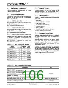
TABLE 10-1: WDT OPERATING MODES
When a WDT time-out occurs while the device is in
Sleep, no Reset is generated. Instead, the device wakes
up and resumes operation. The TO and PD bits in the
STATUS register are changed to indicate the event. See
Section 3.0 “Memory Organization” and STATUS
register (Register 3-1) for more information.
WDTE
Config bits
Device
Mode
WDT
Mode
SWDTEN
WDT_ON (11)
X
X
X
1
0
X
X
Active
Active
WDT_NSLEEP (10)
WDT_NSLEEP (10)
WDT_SWDTEN (01)
WDT_SWDTEN (01)
WDT_OFF (00)
Awake
Sleep Disabled
X
X
X
Active
Disabled
Disabled
TABLE 10-2: WDT CLEARING CONDITIONS
Conditions
WDT
WDTE<1:0> = 00
WDTE<1:0> = 01 and SWDTEN = 0
WDTE<1:0> = 10 and enter Sleep
CLRWDTCommand
Cleared
Oscillator Fail Detected
Exit Sleep + System Clock = T1OSC, EXTRC, INTOSC, EXTCLK
Exit Sleep + System Clock = XT, HS, LP
Cleared until the end of OST
Unaffected
Change INTOSC divider (IRCF bits)
DS41414A-page 104
Preliminary
2010 Microchip Technology Inc.

 MICROCHIP [ MICROCHIP ]