PIC16C63A/65B/73B/74B
4.3
PCL and PCLATH
Note 1: There are no status bits to indicate stack
overflow or stack underflow conditions.
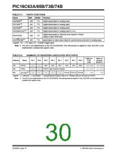
The program counter (PC) is 13-bits wide. The low byte
comes from the PCL register, which is a readable and
writable register. The upper bits (PC<12:8>) are not
readable, but are indirectly writable through the
PCLATH register. On any RESET, the upper bits of the
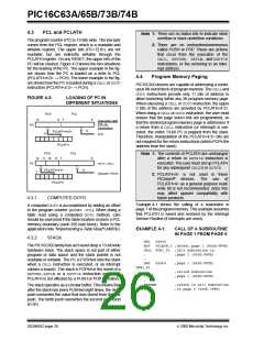
PC will be cleared. Figure 4-3 shows the two situations
for the loading of the PC. The upper example in the fig-
ure shows how the PC is loaded on a write to PCL
(PCLATH<4:0> → PCH). The lower example in the fig-
ure shows how the PC is loaded during a CALLor GOTO
instruction (PCLATH<4:3> → PCH).
2: There are no instructions/mnemonics
called PUSH or POP. These are actions
that occur from the execution of the
CALL, RETURN, RETLW, and RETFIE
instructions, or the vectoring to an inter-
rupt address.
4.4
Program Memory Paging
PIC16CXX devices are capable of addressing a contin-
uous 8K word block of program memory. The CALLand
GOTO instructions provide only 11 bits of address to
allow branching within any 2K program memory page.
When executing a CALLor GOTOinstruction, the upper
2 bits of the address are provided by PCLATH<4:3>.
When doing a CALLor GOTOinstruction, the user must
ensure that the page select bits are programmed, so
that the desired program memory page is addressed. If
a return from a CALL instruction (or interrupt) is exe-
cuted, the entire 13-bit PC is popped from the stack.
Therefore, manipulation of the PCLATH<4:3> bits are
not required for the return instructions (which POPs the
address from the stack).
FIGURE 4-3:
LOADING OF PC IN
DIFFERENT SITUATIONS
PCH
PCL
12
8
7
0
Instruction with
PCL as
Destination
PC
8
PCLATH<4:0>
PCLATH
5
ALU
PCH
12 11 10
PC
PCL
Note 1: The contents of PCLATH are unchanged
after a return or RETFIE instruction is
executed. The user must set up PCLATH
for any subsequent CALL’s or GOTO’s
8
7
0
GOTO,CALL
PCLATH<4:3>
PCLATH
11
2
Opcode <10:0>
2: PCLATH<4> is not used in these
PICmicro® devices. The use of
PCLATH<4> as a general purpose read/
write bit is not recommended, since this
may affect upward compatibility with
future products.
4.3.1
COMPUTED GOTO
Example 4-1 shows the calling of a subroutine in
page 1 of the program memory. This example assumes
that PCLATH is saved and restored by the Interrupt
Service Routine (if interrupts are used).
A computed GOTOis accomplished by adding an offset
to the program counter (ADDWF PCL). When doing a
table read using a computed GOTO method, care
should be exercised if the table location crosses a PCL
memory boundary (each 256 byte block). Refer to the
application note “Implementing a Table Read" (AN556).
EXAMPLE 4-1:
CALL OF A SUBROUTINE
IN PAGE 1 FROM PAGE 0
4.3.2
STACK
ORG
BSF
0x500
PCLATH,3 ;Select page 1 (800h-FFFh)
The PIC16CXX family has an 8-level deep x 13-bit wide
hardware stack. The stack space is not part of either
program or data space and the stack pointer is not
readable or writable. The PC is PUSHed onto the stack
when a CALL instruction is executed, or an interrupt
causes a branch. The stack is POPed in the event of a
RETURN,RETLW or a RETFIE instruction execution.
PCLATH is not affected by a PUSH or POP operation.
CALL SUB1_P1 ;Call subroutine in
:
;page 1 (800h-FFFh)
:
ORG
0x900
;page 1 (800h-FFFh)
SUB1_P1
:
:
:
;called subroutine
;page 1 (800h-FFFh)
RETURN
;return to Call subroutine
;in page 0 (000h-7FFh)
The stack operates as a circular buffer. This means that
after the stack has been PUSHed eight times, the ninth
push overwrites the value that was stored from the first
push. The tenth push overwrites the second push (and
so on).
DS30605C-page 26
2000 Microchip Technology Inc.

 MICROCHIP [ MICROCHIP ]