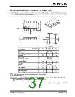
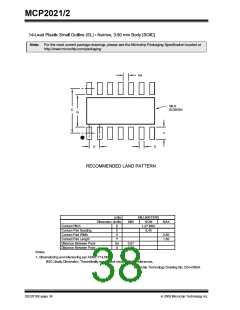
MCP2021/2
Revision B (August 2007)
APPENDIX A: REVISION HISTORY
The following is the list of modifications:
1. Modified Block Diagram on page 2.
Revision E (February 2009)
The following is the list of modifications.
2. Section 1.3.5 “Transmitter OFF Mode”:
Deleted text in 1st paragraph.
1. Added Example 1-2 and Example 1-3.
3. Example 1-1: Removed +5V notation.
2. Updated Section 1.5.9 “RESET”.
4. Section 1.5 “Pin Descriptions”: Removed 10-
3. Updated Section 1.7 “ICSP™ Consider-
ations”.
pin DFN, MSOP column from table.
5. Section 1.5.8 “Fault/TXE”: Deleted text from
4. Updated Section 2.1 “Absolute Maximum
Ratings†”.
2nd paragraph.
6. Section 3.0 “Packaging Information”: Added
8-lead 4x4 and 6x5 DFN and 14-lead TSSOP
packages. Updated package outline drawings
and added drawings for 8-lead DFN and 14-lead
TSSOP drawings.
5. Updated Section 2.2 “DC Specifications” and
Section 2.3 “AC Specification”.
6. Added FIGURE 2-3: “ESR Curves For Load
Capacitor Selection”.
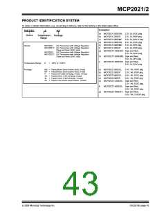
7. Updated the Product Identification System
section.
Revision A (November 2005)
Revision D (July 2008)
• Original Release of this Document.
The following is the list of modifications.
1. Updated ESD specs under ‘Absolute DC’.
2. Updated notes in Example 1-1.
3. Updated Package Outline Drawings.
Revision C (April 2008)
The following is the list of modifications.
1. Added LIN2.1 and J2602 compliance statement
to Features section.
2. Added recommended RC network for CS/
LWAKE in Example 1-1.
3. Updated 2.1 Absolute Maximum Ratings to
reflect current test results.
4. Updated 2.2 DC Specifications and 2.3 AC
Specifications to reflect current production
device.
5. Added 8-Lead SOIC Landing Pattern Outline
drawing.
© 2009 Microchip Technology Inc.
DS22018E-page 41

 MICROCHIP [ MICROCHIP ]