HCS301
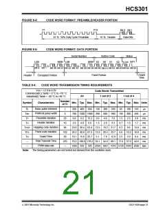
FIGURE 8-4:
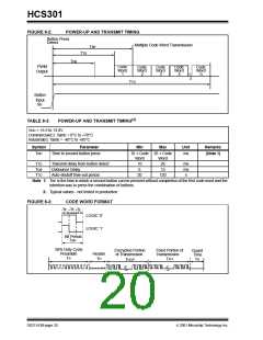
CODE WORD FORMAT: PREAMBLE/HEADER PORTION
P1
P12
Bit 0 Bit 1
23 TE 50% Duty Cycle Preamble
10 TE Header
Data Bits
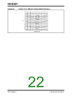
FIGURE 8-5:
CODE WORD FORMAT: DATA PORTION
Serial Number
Button Code
S0 S1
Status
LSB
Bit 0 Bit 1
Encrypted Portion
MSB LSB
MSB S3
S2 VLOW RPT
Bit 30 Bit 31 Bit 32 Bit 33 Bit 58 Bit 59 Bit 60
Bit 62 Bit 63 Bit 64 Bit 65
Bit 61
Fixed Portion
Guard
Time
Header
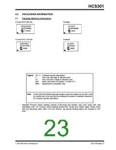
TABLE 8-4:
CODE WORD TRANSMISSION TIMING REQUIREMENTS
VDD = +2.0 to 6.0V
Commercial(C):Tamb = 0 °C to +70 °C
Industrial(I):Tamb = -40 °C to +85 °C
Code Words Transmitted
1 out of 2
All
1 out of 4
Number
of TE
Symbol
Characteristic
Min. Typ. Max. Min. Typ. Max. Min. Typ. Max. Units
Basic pulse element
PWM bit pulse width
Preamble duration
Header duration
TE
TBP
TP
1
260
400
660
130
200
600
4.6
330
990
7.6
65
195
1.5
0.7
6.2
6.6
2.5
100
300
2.3
1.0
9.6
165
495
3.8
µs
µs
3
780 1200 1980 390
23
10
96
102
39
270
—
6.0
2.6
9.2
4.0
15.2
6.6
3.0
1.3
ms
ms
ms
ms
ms
ms
TH
2.0
3.3
1.7
Hopping code duration
Fixed code duration
Guard Time
THOP
TFIX
TG
25.0 38.4 63.4 12.5 19.2 31.7
26.5 40.8 67.3 13.3 20.4 33.7
15.8
10.2 16.8
3.9 6.4
10.1 15.6 25.7
5.1
7.8
12.9
Total Transmit Time
PWM data rate
—
70.2 108.0 178.2 35.1 54.0 89.1 17.6 27.0 44.6
1282 833
—
505 2564 1667 1010 5128 3333 2020 bps
Note: The timing parameters are not tested but derived from the oscillator clock.
2001 Microchip Technology Inc.
DS21143B-page 21

 MICROCHIP [ MICROCHIP ]