July 1999
ML4903
High Current Synchronous Buck Controller
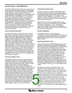
GENERAL DESCRIPTION
FEATURES
The ML4903 high current synchronous buck controller
■ Designed to meet Pentium Pro and Pentium II VRM
provides high efficiency DC/DC conversion to generate
power supply requirements
®
V
CCP
for processors such as the Pentium Pro and Pentium
®
II from Intel .
■ DC regulation to +1% maximum
The ML4903 controller, when combined with two external
MOSFETs, generates output voltages between 1.8V and
3.5V from a 12V supply. The output voltage is selected via
an internal 2 chord 4-bit DAC. In the upper range, the
output can be set between 2.1V and 3.5V in 100mV steps.
In the lower range, the output can be set between 1.8V
and 2.05V in 50mV steps. Output currents in excess of
20A can be attained at efficiencies greater than 80%.
■ Proprietary circuitry provides transient response of ±5%
maximum over a 0A to 14A load range
■ Programmable output voltage (1.8V to 3.5V) is set by
an onboard 2 chord 4-bit DAC
■ Synchronous buck topology for maximum power
conversion efficiency
The ML4903 can be enabled/disabled via the SHDN pin.
While disabled, the output of the regulator is completely
isolated from the circuit’s input supply. The ML4903
employs fixed-frequency PWM control combined with a
sophisticated control loop enhancement circuit to provide
excellent load transient response.
■ Fixed frequency operation for easier system integration
■ Integrated anti-shootthrough logic, short circuit
protection, shutdown, and UV lockout
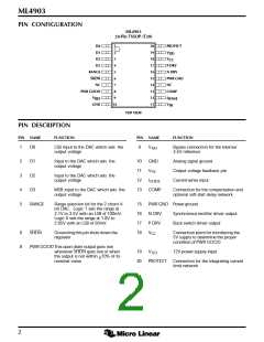
BLOCK DIAGRAM
V
DD
19
+
–
10.5V
4.4V
P DRV
UVLO
V
CC
17
18
+
–
CONTROL
LOGIC
N DRV
16
5V
30µA
+
–
3.5V
+
PROTECT
PWR GND
20
15
13
11
–
COMP
SHDN
D0
200kHz
6
1
2
3
4
V
FB
–
+
V
DAC
D1
+
–
-107mV
D2
I
SENSE
12
8
D3
PWR GOOD
RANGE
2 CHORD
4 BIT DAC
5
V
V
+ 10%
DAC
DAC
+
–
V
+ 3%
DAC
+
–
V
+ 3%
DAC
V
FB
V
REF
3.5V
REFERENCE
+
–
9
V
FB
V
- 10%
- 3%
DAC
+
–
V
- 3%
V
DAC
DAC
GND
10
1

 MICRO-LINEAR [ MICRO LINEAR CORPORATION ]