MIC37100/37101/37102
Micrel
900
800
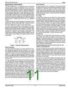
Using Figure 4, the minimum amount of required copper can
be determined based on the required power dissipation.
Power dissipation in a linear regulator is calculated as fol-
lows:
∆TJA
=
700
600
500
400
300
200
100
0
P = (V – V
) I
+ V × I
D
IN
OUT OUT IN GND
If we use a 2.5V output device and a 3.3V input at an output
current of 1A, then our power dissipation is as follows:
P = (3.3V – 2.5V) × 1A + 3.3V × 11mA
D
P = 800mW + 36mW
D
0
0.25 0.50 0.75 1.00 1.25 1.50
POWER DISSIPATION (W)
P = 836mW
D
From Figure 4, the minimum amount of copper required to
operate this application at a ∆T of 75°C is 160mm .
Figure 4. Copper Area vs. Power SO-8
Power Dissipation
2
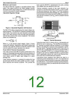
Quick Method
Figure 4 shows copper area versus power dissipation with
each trace corresponding to a different temperature rise
above ambient.
Determine the power dissipation requirements for the design
along with the maximum ambient temperature at which the
device will be operated. Refer to Figure 5, which shows safe
operating curves for three different ambient temperatures:
25°C, 50°C and 85°C. From these curves, the minimum
amount of copper can be determined by knowing the maxi-
mum power dissipation required. If the maximum ambient
temperature is 50°C and the power dissipation is as above,
836mW, the curve in Figure 5 shows that the required area of
From these curves, the minimum area of copper necessary
for the part to operate safely can be determined. The maxi-
mum allowable temperature rise must be calculated to deter-
mine operation along which curve.
∆T = T (max) – T (max)
J
A
T (max) = 125°C
J
2
copper is 160mm .
T (max) = maximum ambient operating temperature
A
The θ of this package is ideally 63°C/W, but it will vary
JA
Forexample, themaximumambienttemperatureis50°C, the
∆T is determined as follows:
depending upon the availability of copper ground plane to
which it is attached.
∆T = 125°C – 50°C
∆T = 75°C
900
T
= 125°C
800
700
600
500
400
300
200
100
0
J
TA = 85°C
50°C 25°C
0
0.25 0.50 0.75 1.00 1.25 1.50
POWER DISSIPATION (W)
Figure 5. Copper Area vs. Power-SOIC
Power Dissipation
September 2004
13
M9999-091604

 MICREL [ MICREL SEMICONDUCTOR ]