Micrel, Inc.
MIC2786/MIC2787
Application Information
Dual Manual Reset Inputs (/MR0, /MR1)
The /MR0, /MR1 input pins have integrated pull-up
resistors for the MIC2786 but require external pull-up
resistors for the MIC2787. A recommended value is
100kΩ to keep the current consumption low when the
push-button switches are pressed. The behavior of the
reset outputs is independent of the order in which the
/MR0, /MR1 inputs are driven low. If both inputs are low
for a setup delay time, only one reset pulse, of width
tRESET, is generated. Keeping both inputs low for a
longer time does not generate additional reset output
pulses.
Design and Product Advantages
The MIC2786/MIC2787 are voltage supervisor reset ICs
with dual manual reset inputs and long manual reset
setup delay times. The dual manual reset inputs and
long manual reset setup delay times help protect against
accidental system resets in applications such as smart
phones, personal navigation devices, MP3 players, and
set-top boxes (STB).
The MIC2786/MIC2787 assert and hold a reset when the
supply voltage decreases below the factory-programmed
threshold voltage. Reset is asserted for a fixed reset
timeout delay once the supply voltage increases above
the rising threshold voltage or when both manual reset
inputs are asserted low for longer than the setup delay
time.
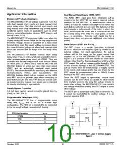
Reset Outputs (/RST and RSTP)
The /RST output is a simple open-drain N-channel
MOSFET structure that requires a pull-up resistor to an
external voltage. For most applications, the pull-up
voltage will be the same as the power supply that
supplies VIN to the MIC2786/MIC2787. As shown in
Figure 1, it is possible to tie this resistor to some other
voltage, other than VIN, thus enabling level-shifting of the
/RST output. The pull-up voltage must be limited to 5.5V
or less to avoid damage to the MIC2786/MIC2787. The
pull-up resistor must be small enough to supply current
to the inputs and leakage paths that are driven by the
/RST output (a recommended value is 100kΩ). Leave
floating if the /RST pin is unused.
The MIC2786/MIC2787 feature manual reset setup
delay times of 2s, 4s or 6s, which are selected by the tri-
state programmable delay input pin (PDY). They are
available with factory-programmed reset timeout delays
of 140ms (min.) or 240ms (min.). Both the MIC2786 and
MIC2787 feature an active-low, open-drain reset output
(/RST) and an active-high, push-pull reset output
(RSTP). This allows flexibility for interfacing with different
microprocessors, PMICs, and load-switches. The
MIC2786 features 65kΩ pull-up resistors on the /MR0
and /MR1 inputs to provide ease when connecting to
push-button inputs. The MIC2787 does not provide pull-
up resistors on the manual reset inputs and is intended
for directly interfacing to logic outputs.
Since the /RST output is open-drain, several reset
sources can be wire-ORed, in parallel, to allow resets
from multiple sources. By tying the pull-up resistor to
some other voltage, the MIC2786/MIC2787 can monitor
one voltage while level-shifting the /RST output to some
other voltage.
Supply Bypass Capacitor
A 0.1µF input bypass capacitor must be placed from VIN
(Pin 8) to GND (Pin 2).
The RSTP pin is a push-pull output that is driven to VIN.
It cannot be level-shifted to another voltage. It is an
inverted signal of /RST.
Programmable Delay Input (PDY)
The MIC2786/MIC2787 has a programmable setup
delay time, tSETUP that is set via a tri-state logic
configuration. The PDY pin is intended to be connected
to the VIN supply voltage, ground or left floating.
PDY Configuration
tSETUP
2s
OPEN
GND
VIN
4s
6s
Figure 1. MIC2786/MIC2787 Used in Multiple Supply
System
M9999-102711-A
October 2011
10

 MICREL [ MICREL SEMICONDUCTOR ]