Micrel
MIC2586/MIC2586R
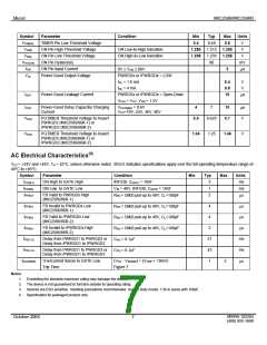
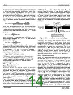
the control element in a circuit that lowers the current limit as
a function of the output voltage. When the load current
increases to the point where the output voltage at the load
approaches 0V (likewise, the MIC2586/MIC2586R’s FB pin
voltage also approaches 0V), the result is a proportionate
decrease in the maximum current allowed into the load. This
foldback current limit subcircuit’s transfer characteristic is
shown in Figure 1. Under excessive load conditions (output
and FB voltage equals 0V), the foldback current limiting
circuit controls the MIC2586/MIC2586R’s GATE drive to
force a constant 12mV (typical) voltage drop across the
external sense resistor.
the time it takes to charge the total load capacitance.
An initial value for CTIMER is found by calculating the time it
will take for the MIC2586/MIC2586R to completely charge up
the output capacitive load. Assuming the load is enabled by
the PWRGDx (or /PWRGDx) signal(s) of the controller, the
turn-on delay time is derived from the following expression, I
= C × (dV/dt):
CLOAD × VCC(MAX)
tTURN-ON
=
(5)
ILIMIT
Using parametric values for the MIC2586/MIC2586R, an
expression relating a worse-case design value for CTIMER
,
using the MIC2586/MIC2586R specification limits, to the
circuit's turn-on delay time is:
Circuit Breaker Operation
The MIC2586/MIC2586R employ an electronic circuit breaker
that protects the external N-channel power MOSFET and
other system components against large-scale output current
faults, both during initial card insertion or during steady-state
operation. The current-limit threshold is set via an external
resistor, RSENSE, connected between the circuit’s VCC pin and
SENSE pin. For the MIC2586/MIC2586R, a fault current
timing circuit is set via an external capacitor (CTIMER) that
determines the length of the time delay (tFLT) for which the
controller remains in current limit before the circuit breaker is
tripped. Programming the response time of the overcurrent
detector helps to prevent nuisance tripping of the circuit
breaker because of high inrush currents charging bulk and
tTURN-ON ×ITIMERUP(MAX)
CTIMER(MAX)
=
VTIMERH(MIN)
120µA
1.280V
⎛
⎜
⎞
⎟
CTIMER(MAX) = tTURN-ON
×
⎝
⎠
µ
sec
F
⎛
⎞
⎟
CTIMER(MAX) = tTURN-ON × 94×10-6
(6)
⎜
⎝
⎠
For example, in a system with a CLOAD = 1000µF, a maximum
VCC = +72V, and a maximum load current on a nominal +48V
buss of 1.65A, the nominal circuit design equations steps
are:
1. Choose ILIMIT = IHOT_SWAP(nom) = 2A (1.65A + 20%);
distributed capacitive loads.
The nominal ovecurrent
2. Select an RSENSE (Closest 1% standard value is
response time is calculated using the following equation:
19.6mΩ);
CFILTER × VTIMERH
tFLT(ms) =
3. Using ICHARGE = ILIMIT = 2A, the application circuit turn-
on time is calculated using Equation 5:
ITIMERUP
tFLT(ms) = 20×CFILTER(µF)
(4)
1000µF× 72V
(
)
tTURN-ON
=
= 36ms
Whenever the voltage across RSENSE exceeds the
MIC2586/MIC2586R’s nominal circuit breaker threshold
voltage of 47mV during steady-state operation, two things
occur:
2A
Allowing for capacitor tolerances and a nominal 36ms turn-on
time, an initial worse-case value for CTIMER is:
µF
⎛
⎞
⎟
CTIMER(MAX) = 0.036s × 94×10-6
= 3.38µF
1. A constant-current regulation loop will engage within
1µs after an overcurrent condition is detected by
⎜
sec
⎝
⎠
R
SENSE, and the control loop is designed to hold the
The closest standard ±5% tolerance capacitor value is 3.3µF
and would be a good initial starting value for prototyping.
voltage across RSENSE equal to 47mV. This feature
protects both the load and the MIC2586/MIC2586R
circuits from excessively high currents.
Whenever the MIC2586 is not in current limit, CTIMER is
discharged to GND by an internal 3.5µA current sink
(ITIMERDN).
2. Capacitor CTIMER is then charged up to the VTIMERH
threshold (1.313V) by an internal 65µA current
source (ITIMERUP). If the excessive current persists
such that the voltage across CTIMER crosses the
VTIMERH threshold, the circuit breaker trips and the
GATE pin is immediately pulled low by a 30mA
(minimum) internal current sink. This operation turns
off the MOSFET quickly and disconnects the input
from the load. The value of CTIMER should be selected
to allow the circuit's minimum regulated output
current (IOUT) to equal ILIMIT for somewhat longer than
For the MIC2586R, the circuit breaker automatically resets
after (20) tFLT_AUTO time constants. If the fault condition still
exists, capacitor CTIMER will begin to charge up to the VTIMERH
threshold, and if exceeded, trip the circuit breaker. Capacitor
CTIMER will then be discharged by ITIMERDN until the voltage
across CTIMER drops below the VTIMERL threshold, at which
time another start cycle is initiated. This will continue until
either of the following occurs: a) the fault condition is
removed, b) the input supply voltage power is
M9999-102204
(408) 955-1690
October 2004
11

 MICREL [ MICREL SEMICONDUCTOR ]