MIC2536
Micrel
Universal Serial Bus (USB) Power Distribution
Applications
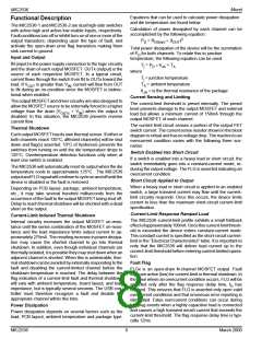
maynotconsumemorethan500µA. Inanonconfiguredstate
all downstream devices will be switched off. In most cases, a
nonconfigured hub is not a practical state for the system.
Therefore, the 2.5mA specification is the applicable target
specification for the suspend state. In a bus-powered hub
with less than 4 ports, the hub may use the additional current
for internal functions.
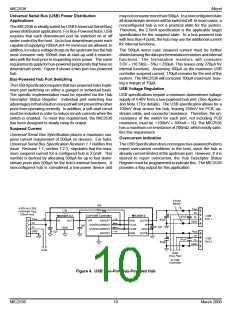
The MIC2536 is ideally suited for USB (Universal Serial Bus)
powerdistributionapplications. ForBus-Poweredhubs, USB
requires that each downstream port be switched on or off
under control by the host. Up to four downstream ports each
capableofsupplying100mAat4.4Vminimumareallowed. In
additon, toreducevoltagedroopontheupstreambusthehub
must consume only 100mA max at start-up until it enumer-
ates with the host prior to requesting more power. The same
requirementsapplyforbus-poweredperipheralsthathaveno
downstream ports. Figure 4 shows a two-port bus-powered
hub.
The 500µA worst case suspend current must be further
dividedamongthedataportterminationresistorsandinternal
functions. The termination resistors will consume
3.6V ÷ (16.5KΩ – 5%) = 230µA. This leaves only 270µA for
internal functions. Assuming 100µA as the maximum USB
controller suspend current, 170µA remains for the rest of the
system. The MIC2536 will consume 100µA maximum, leav-
ing a margin of 70µA.
Bus-Powered Hub Port Switching
TheUSBSpecificationrequiresthatbus-poweredhubsimple-
ment port switching on either a ganged or individual basis.
The specific implementation must be reported via the Hub
Descriptor Status Register. Individual port switching has
advantagesinthatafaultononeportwillnotpreventtheother
ports from operating correctly. In addition, a soft-start circuit
must be included in order to reduce inrush currents when the
switch is enabled. To meet this requirement, the MIC2536
has been designed to slowly ramp its output.
USB Voltage Regulation
USB specifications require a minimum downstream voltage
supply of 4.40V from a bus-powered hub port (See Applica-
tion Note 17 for details). The USB specification allows for a
100mV drop across the hub, leaving 250mV for PCB, up-
stream cable, and connector resistance. Therefore, the on-
resistance of the switch for each port, not including PCB
resistance, must be <100mV ÷ 100mA = 1Ω. The MIC2536
has a maximum on-resistance of 700mΩ, which easily satis-
fies this requirement.
Suspend Current
Universal Serial Bus Specification places a maximum sus-
pend current requirement of 500µA on devices. For hubs,
Universal Serial Bus Specification Revision 1.1 clarifies this
issue. Revision 1.1, section 7.2.3, stipulates that the maxi-
mum suspend current for a configured hub is 2.5mA. This
number is derived by allocating 500µA for up to four down-
stream ports plus 500µA for the hub’s internal functions. A
nonconfigured hub is considered a low-power device and
Overcurrent Indication
TheUSBSpecificationdoesnotrequirebus-poweredhubsto
report overcurrent conditions to the host, since the hub is
already current-limited at the upstream port. However, if it is
desired to report overcurrent, the Hub Descriptor Status
Register must be programmed to indicate this. The MIC2536
provides a flag output for this application.
Ferrite
Beads
10k
4.50V to 5.25V
Upstream VBUS
100mA max.
VBUS
1.5k
10k
D+
3.3V USB Controller
MIC2536-2
MIC5207-3.3
USB
Port 1
.01µF
.01µF
D–
VBUS
D+
63µF
0.1µF
VIN
IN
OUT
ON/OFF
ENA
OUTA
IN
GND
OVERCURRENT
OVERCURRENT
ON/OFF
FLGA
FLGB
ENB
1µF
D–
GND
GND
OUTB
VBUS
D+
GND
4.7µF
USB
Port 2
D–
63µF
GND
Data
Data
(Two Pair)
to USB
Controller
Figure 4. USB Two-Port Bus-Powered Hub
MIC2536
10
March 2000

 MICREL [ MICREL SEMICONDUCTOR ]