2. POWER-DOWN mode
The user can set the bit PCON.1 to drive this chip entering POWER-DOWN mode.
In the POWER-DOWN mode, the on-chip oscillator is stopped. The contents of on-chip RAM and
SFRs are maintained.
The power-down mode can be woken-up by either hardware reset or /INT0, /INT1, /INT2 and
/INT3 external interrupts. When it is woken-up by RESET pin, the program will execute from the
address 0x0000, and be carefully to keep RESET pin active for at least 10ms in order to get a
stable clock while waking up this chip from POWER-DOWN mode. If it is woken-up from I/O, the
program will jump to related interrupt service routine. To use I/O wake-up, interrupt-related
registers have to be programmed accurately before power-down is entered. Pay attention to
add at least one “NOP” instruction subsequent to the power-down instruction if I/O
waken-up is used.
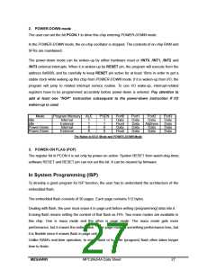
Mode
Program Memory ALE
PSEN
Port0
Data
Float
Data
Float
Port1
Data
Data
Data
Data
Port2
Data
Address
Data
Data
Port3
Data
Data
Data
Data
Idle
Idle
Internal
External
Internal
External
1
1
0
0
1
1
0
0
Power-Down
Power-Down
Pin Status in IDLE Mode and POWER-DOWN Mode
3. POWER-ON FLAG (POF)
The register bit in PCON.4 is set only by power-on action. System RESET from watch-dog-timer,
software RESET and RESET pin can not set this bit. It can be cleared by firmware.
In System Programming (ISP)
To develop a good program for ISP function, the user has to understand the architecture of the
embedded flash.
The embedded flash consists of 30 pages. Each page contains 512 bytes.
Dealing with flash, the user must erase it in page unit before writing (programming) data into it.
Erasing flash means setting the content of that flash as FFh. Two erase modes are available in
this chip. One is mass mode and the other is page mode. The mass mode gets more
performance, but it erases the entire flash. The page mode is something performance less, but
it is flexible since it erases flash in page unit.
Unlike RAM’s real-time operation, to erase flash or to write (program) flash often takes longer
time to finish.
MEGAWIN
MPC89x54A Data Sheet
27

 MEGAWIN [ MEGAWIN TECHNOLOGY CO., LTD ]