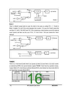
Interrupt
There are eight interrupt sources available in MPC89x54A. Each interrupt source can be
individually enabled or disabled by setting or clearing a bit in the SFR named IE. This register
also contains a global disable bit (EA), which can be cleared to disable all interrupts at once.
Each interrupt source has two corresponding bits to represent its priority. One is located in SFR
named IPH and the other in IP/XICON register. Higher-priority interrupt will be not interrupted by
lower-priority interrupt request. If two interrupt requests of different priority levels are received
simultaneously, the request of higher priority is serviced. If interrupt requests of the same priority
level are received simultaneously, an internal polling sequence determines which request is
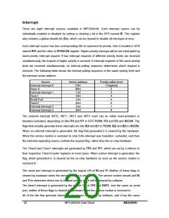
serviced. The following table shows the internal polling sequence in the same priority level and
the interrupt vector address.
Source
External interrupt 0
Timer 0
External interrupt 1
Timer1
Serial Port
Timer2
External interrupt 2
External interrupt 3
Vector address
03H
Priority within level
1 (highest)
0BH
13H
1BH
23H
2BH
33H
3BH
2
3
4
5
6
7
8
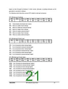
The external interrupt /INT0, /INT1, /INT2 and /INT3 each can be either level-activated or
transition-activated, depending on bits IT0 and IT1 in SFR TCON, IT2 and IT3 and XICON. The
flags that actually generate these interrupts are bits IE0 and IE1 in TCON, IE2 and IE3 in XICON.
When an external interrupt is generated, the flag that generated it is cleared by the hardware.
When the service routine is vectored to only if the interrupt was transition –activated, and then
the external requesting source controls the request flag, rather than the on-chip hardware.
The Timer0 and Timer1 interrupts are generated by TF0 and TF1, which are set by a rollover in
their respective Timer/Counter registers in most cases. When a timer interrupt is generated, the
flag, which generated it, is cleared by the on-chip hardware as soon as the service routine is
vectored to.
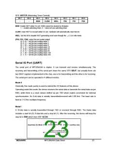
The serial port interrupt is generated by the logical OR of RI and TI. Neither of these flags is
cleared by hardware when the service routine is vectored to. The service routine should poll RI
and TI to determine which one to request service and it will be cleared by software.
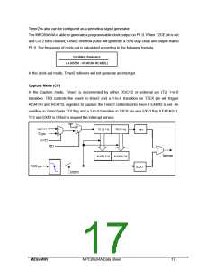
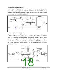
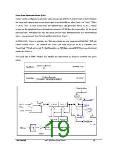
The timer2 interrupt is generated by the logical OR of TF2 and EXF2. Just the same as serial
port, neither of these flags is cleared by hardware when the service routine is vectored to.
All of the bits that generate interrupts can be set or cleared by software, and it has the same
20
MPC89x54A Data Sheet
MEGAWIN

 MEGAWIN [ MEGAWIN TECHNOLOGY CO., LTD ]